
Table of Contents
- What Is Polar Alignment in Astrophotography?
- Why Polar Alignment Accuracy Matters: Tracking, Guiding, and Field Rotation
- Essential Gear and Setup Considerations for Reliable Polar Alignment
- Step-by-Step Methods: From Rough to Precision Polar Alignment
- Hemisphere-Specific Tips: North vs South Celestial Pole
- Error Sources and How to Quantify Them in Arcseconds and Pixels
- Troubleshooting Stubborn Polar Alignment Problems
- Advanced Techniques: Sky Modeling, Refraction Compensation, and Unguided Imaging
- Frequently Asked Questions
- Final Thoughts on Choosing the Right Polar Alignment Method
What Is Polar Alignment in Astrophotography?
Polar alignment is the process of orienting an equatorial mount (or a star tracker’s right ascension axis) so that it is parallel to Earth’s axis of rotation and points at the celestial pole. In the Northern Hemisphere, that axis points near Polaris; in the Southern Hemisphere, it points near the relatively dim star Sigma Octantis. By aligning the mount’s right ascension (RA) axis with the sky’s axis, the mount can rotate in the opposite direction of Earth’s spin, allowing long exposures that hold stars as points instead of streaks.

Artist: Negadrive
This seemingly simple setup step underpins nearly every form of deep-sky imaging and long-exposure nightscape photography. Whether you are capturing a 30-second Milky Way panorama with a compact star tracker or a 10-minute narrowband subframe with a cooled astro camera on a computerized mount, polar alignment determines how effectively your system cancels Earth’s rotation. It also sets the foundation for autoguiding performance and sky modeling, and it reduces the risk of field rotation—a phenomenon where stars rotate around the image center during a single exposure when alignment is off.
For many beginners, polar alignment sounds intimidating. The good news is there are multiple reliable approaches—from simple sighting through a polar scope to highly precise plate-solving workflows in software. In this guide, we cover practical, repeatable methods, show how to estimate the accuracy you need, and offer fixes for the most common stumbling blocks. If you are deciding among methods, jump ahead to Step-by-Step Methods. If you are stuck, go straight to Troubleshooting.
Why Polar Alignment Accuracy Matters: Tracking, Guiding, and Field Rotation
At its core, polar alignment removes rotational motion in the sky by turning the mount’s RA axis at the sidereal rate. If the RA axis is not parallel to Earth’s axis, the mount will still track stars roughly, but several problems arise:
- RA/Dec cross-talk: Misalignment causes drift primarily in declination (Dec). Autoguiding can correct this drift to a point, but it uses up guiding bandwidth that could otherwise correct seeing or periodic error.
- Field rotation within a single exposure: Even if autoguiding keeps your guide star centered, the rest of the frame can rotate around that point when polar alignment is off, softening stars away from the guide star. This is especially visible at the edges of wide fields and with longer exposures.
- Uneven performance across the sky: Polar misalignment affects targets differently depending on where you point. Near the meridian and celestial equator, drift is more apparent. Close to the pole, it may be less obvious but still present.
- Mount strain and guiding instability: Guiding algorithms prefer small, random errors to correct. Systematic drift from poor alignment means continuous, one-directional corrections that aggravate backlash and mechanical play.
How accurate is “good enough”? That depends on focal length, pixel scale, exposure length, and whether you are guiding. As we quantify in Error Sources and How to Quantify Them, a few arcminutes of error may be acceptable at 24–50 mm for landscape tracking, but at 600–1000 mm focal length you generally benefit from sub-arcminute alignment, especially for multi-minute subexposures.
Rule of thumb: The more you magnify the sky (longer focal length, smaller pixels), the tighter your polar alignment needs to be to keep stars round across the field, even with guiding.
Essential Gear and Setup Considerations for Reliable Polar Alignment
A successful alignment session begins with a stable, repeatable setup. Small mechanical issues can masquerade as alignment problems, so address the basics first:
- Solid tripod or pier: Use a rigid support with firm ground contact. On soil, consider ground spikes. On hard surfaces, avoid vibration-prone decking.
- Mount altitude/azimuth adjusters: Smooth, backlash-minimized adjusters make fine tweaks easier. If your mount’s bolts gall or stick, apply appropriate lubrication and never overtighten.
- Polar scope or alignment camera: Many equatorial heads include a polar scope with an etched reticle. Others ship with (or support) electronic alignment cameras like PoleMaster or iPolar that present the polar region on-screen.
- Imaging or guide camera for software-assisted methods: Apps such as Sharpcap and NINA can use your main camera or guide camera to plate-solve and compute the alignment error vector.
- Power and cables: Ensure cables have enough slack for azimuth and altitude adjustments. Cable tension can tug the RA axis, shifting your alignment after you think you’ve nailed it.
- Clear view of the pole: Buildings or trees near the pole direction complicate alignment. If your northern or southern horizon is blocked, plan to use a drift or plate-solve method that points away from the pole.

Artist: HiyoriX
Two other setup details matter more than their reputation implies:
- Balance matters after alignment: While balance does not directly affect polar alignment, rebalancing after major adjustments avoids mount slip during the session.
- Time and location accuracy: For methods using sky models or alt-az to equatorial conversions, ensure your mount or app has accurate GPS/location and time (including time zone and daylight saving settings).
For portable rigs, consider building a routine checklist you can run quickly every setup. See the configuration checklist in Step-by-Step Methods.
Step-by-Step Methods: From Rough to Precision Polar Alignment
Different nights call for different tools. A quick Milky Way session with a star tracker in Bortle 7 skies? Use a smartphone-assisted rough alignment and a software refinement. A deep-sky target at 800 mm for five-minute subs? Step up to plate-solving or drift alignment. Below are practical methods, in the order many astrophotographers progress through them.
Rough Daytime and Twilight Alignment
You can get close before dark and save time. This is especially useful for field setups and star trackers without electronic aids.
- Compass and inclinometer: Set your mount to your site’s latitude using the altitude scale and point the azimuth roughly toward true north/south. Remember that magnetic north is not true north; consider your local magnetic declination (available via mapping apps). Metal in the tripod can skew a compass; hold it away from the mount.
- Solar noon method: Around local solar noon, align the mount’s azimuth so the Sun’s RA circle is centered along the RA axis shadow. Use a solar filter or the shadow-only technique; never look at the Sun directly.
- Using landmarks: If you have a fixed observing spot, note a distant landmark that lines up with the pole. Over time you can set the azimuth by eye within a degree or two.
These rough methods are not “done,” but they can place you within a few degrees, making fine methods faster. Next, move to an optical or software-based refinement.
Using a Polar Scope and Reticle

Artist: Gn842
A polar scope provides a reticle showing the circle around the pole, with markings for asterisms or Polaris position. Accuracy depends on properly collimating the polar scope to the mount’s RA axis and placing Polaris (or the sigma Octantis asterism) correctly based on the current time and date.
- Calibrate the reticle: During the day, point the RA axis to a distant object and rotate the RA axis 180°. The object should trace a circle centered on the reticle’s center. Adjust the polar scope alignment screws until the circle is minimized.
- Set reticle orientation: At night, rotate the RA axis to match the reticle orientation with the sky (many reticles assume 0° at the top when the counterweight points straight down).
- Place Polaris: Use a phone app or the reticle’s clock to place Polaris on the small circle offset from the center. Remember, Polaris is about 0.7° from the true pole; it should not go at the center.
Well-collimated polar scopes can reach 2–5 arcminutes of accuracy in practiced hands—often good enough for short- to medium-focal-length imaging and especially for portable rigs. For even better precision, move to plate-solving or drift alignment.
Sharpcap Polar Alignment (Camera-Based Plate Solving)
Sharpcap Pro’s polar alignment tool uses your main or guide camera to image the region near the pole, plate-solve it, and compute the vector between your current mount axis and the true celestial pole. It then provides on-screen arrows guiding your altitude and azimuth bolts.
- Roughly point the mount near the pole and connect your camera in Sharpcap.
- Select Polar Alignment. The software takes a short exposure and plate-solves.
- Sharpcap instructs you to rotate the RA axis by a specified angle (e.g., ~90°). It solves again to determine the RA axis tilt.
- Follow the on-screen vectors to adjust azimuth and altitude until the error reads within your target arcminutes.
Pros: fast, intuitive, and precise—often within 1–2 arcminutes. Cons: requires view near the pole and a Windows computer. If your pole is blocked, see PHD2 Drift Alignment or NINA’s off-pole methods.
NINA Three-Point Polar Alignment
NINA’s Three-Point Polar Alignment algorithm plate-solves three camera pointings and computes the mount’s polar axis offset. It is particularly useful when you do not have a clear line of sight to the pole, because the method works away from the pole by rotating the RA axis and sampling the sky.
- Connect your imaging camera and mount in NINA.
- Open the TPPA plugin or built-in tool and follow prompts to capture three points.
- NINA calculates the offset and provides directional guidance for alt/az bolts.
- Iterate until the reported error meets your goals; under 3 arcminutes is straightforward on most setups.
TPPA is excellent if trees block Polaris or Sigma Octantis. If you still struggle to converge, scan Troubleshooting for bolt backlash and flexure issues.
PoleMaster and iPolar (Dedicated Alignment Cameras)
Dedicated alignment cameras mount on the RA axis and present a calibrated, wide-field view of the polar region. Their companion software walks you through a short sequence similar to other plate-solve methods, often with a live, responsive overlay.
- PoleMaster: A popular USB camera system that attaches to many mounts. Its software guides you through star identification and adjustment.
- iPolar: iOptron’s integrated camera in some mounts and as a retrofit. The software is streamlined and requires minimal interaction.
These systems can be very fast—ideal for outreach or quick setups. Their precision typically lands within a couple arcminutes, sufficient for most guided imaging. They do, however, cost extra and require a laptop (unless integrated into a controller).
PHD2 Drift Alignment
Drift alignment is a classic, very precise method that relies on measuring a star’s drift in declination to infer your mount’s polar misalignment. The advantage is that it works even if the pole is obstructed and can reach sub-arcminute precision with patience.
- Choose a star near the meridian and celestial equator: This maximizes sensitivity to azimuth error.
- Disable Dec guiding temporarily: In PHD2, let the star drift while watching its direction.
- Adjust azimuth: Turn the azimuth bolts to null the drift over time.
- Choose a star low in the east or west (~20–30° altitude): This maximizes sensitivity to altitude error.
- Disable Dec guiding again: Adjust the altitude bolt to reduce drift to near zero.
- Iterate both steps as needed; fine adjustments are delicate and benefit from slow, controlled bolt movement.
Pros: extreme accuracy and flexibility. Cons: time-consuming; requires practice to interpret drift direction quickly. If you are new to drift alignment, see the error translation notes in Error Sources and the bolt handling tips in Troubleshooting.
DARV (Drift Alignment by Robert Vice)
DARV is a variant of drift alignment that uses an intentional oscillation in RA to create a V-shaped star trail, which directly shows which way to adjust. Some camera control software can automate the movement and exposure. It is faster than classic drift for many users but not as common as plate-solving today.
All-Star Polar Alignment (ASPA) on Celestron Mounts
ASPA is a hand-controller routine on many Celestron equatorial mounts that slews to a bright star and walks you through centering using the mount’s alt/az bolts (not the hand control). It relies on a good two- or three-star alignment first. It offers convenient refinement without sight of Polaris, though plate-solving methods often edge it in final precision for imaging.
Alt-Az Forks with Wedges and Portable Star Trackers
Alt-az mounts can be placed on a wedge to emulate an equatorial angle. The alignment process is identical in principle: set the wedge latitude, point the azimuth to the pole, and refine. Portable star trackers (e.g., compact equatorial heads) excel at wide-field work but may have coarser adjusters; use a lightweight method like a polar scope plus a quick plate-solve (e.g., smartphone-assisted) to tighten results.
Quick Polar Alignment Checklist
1. Plant tripod firmly; set approximate latitude on the mount.
2. Rough-aim azimuth to true north/south (account for magnetic declination).
3. Attach imaging/guide camera; manage cable slack.
4. Perform rough alignment via polar scope or app.
5. Choose a precision method: Sharpcap, NINA TPPA, PHD2 drift, or dedicated camera.
6. Iterate adjustments gently; recheck after tightening bolts.
7. Rebalance if needed; start guiding or imaging.
If your conditions or equipment limit your options, prioritize a method that works with your sky access. For example, if Polaris is behind a building, jump to NINA Three-Point or PHD2 Drift. If time is short and the pole is clear, Sharpcap or a dedicated camera is hard to beat.
Hemisphere-Specific Tips: North vs South Celestial Pole
While the principles are identical, the sky around each pole differs in convenience.
- Northern Hemisphere (Polaris region): Polaris is bright (magnitude ~2) and close to the true pole. Polar scope reticles often show Polaris’ offset circle and hour-angle markings. Finding Polaris in city skies is usually straightforward.

Polaris (Alpha Ursae Minoris) as seen by the Hubble Space Telescope.
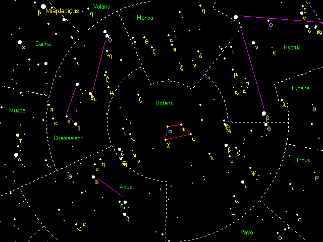
Artist: NASA/HST - Southern Hemisphere (Sigma Octantis region): Sigma Octantis is faint (magnitude ~5.5) and the surrounding asterism is subtler. Reticles include patterns matching Octans, but darker skies or camera-assisted methods (Sharpcap, iPolar, NINA TPPA) ease the process significantly.
General tactics for the south:
Artist: Conrad Leviston
- Use a phone app to overlay the SCP area and practice identifying the Octans trapezoid.
- Lean on plate-solving methods when possible; they remove ambiguity in star identification.
- If you must use a polar scope, let your eyes dark-adapt and use low brightness on any illuminated reticles to avoid washing out faint stars.
For both hemispheres, atmospheric refraction slightly shifts apparent star positions at low altitudes. Most alignment routines that focus near the pole reduce refraction’s impact, but sky models and advanced mounts can explicitly compensate (see Advanced Techniques).
Error Sources and How to Quantify Them in Arcseconds and Pixels
To decide how precise you need to be, translate polar misalignment into what you actually see: star trails or bloated FWHM in your images. This depends on your pixel scale (arcseconds per pixel), exposure time, mount accuracy, and where in the sky you are pointing.
Estimating Pixel Scale and Drift Tolerance
First, compute pixel scale:
Pixel scale (arcsec/pixel) ≈ 206 × (pixel size in µm) / (focal length in mm)
Example: 3.8 µm pixels at 600 mm → 206 × 3.8 / 600 ≈ 1.3 arcsec/pixel
Next, decide how much drift your stars can tolerate within a single exposure before they look elongated. A conservative target is to keep total drift under 0.5–1 pixel RMS during the exposure. If your pixel scale is 2 arcsec/pixel, aim for under 1–2 arcseconds of drift in that timeframe. At 1.3 arcsec/pixel, try to keep drift below about 1 arcsecond per exposure.
How Polar Misalignment Produces Drift and Field Rotation
Polar misalignment manifests as declination drift that varies with pointing and as rotational smear across the field. The exact math is involved, but two practical observations help:
- Meridian/equator test for azimuth error: Drift is maximized near the celestial equator on the meridian. Residual drift here indicates azimuth error. Adjust azimuth to zero it.
- Low east/west test for altitude error: Drift near the eastern or western horizon indicates altitude error. Raise or lower the altitude knob accordingly.
Field rotation rises away from the guide star or frame center and becomes more visible with wider fields and longer exposures. Good polar alignment reduces this rotation everywhere in the frame, not just at the guide star.
Converting Arcminutes of Misalignment to Impact
As a rough guide, around 5–10 arcminutes of misalignment can limit unguided exposures to well under a minute at 300–600 mm before star elongation becomes visible toward the frame edges, whereas guided imaging may tolerate a few arcminutes more if your guide scale is coarser and your exposures are shorter. At ultra-wide focal lengths (14–35 mm), a degree or less of misalignment may still produce usable 30–60 second exposures, especially if the tracker is reasonably smooth.
Tip: If your guiding graph shows persistent Dec corrections in one direction, that’s a clue your polar alignment still has room for improvement. See Troubleshooting for interpreting guiding patterns.
Troubleshooting Stubborn Polar Alignment Problems
Even with good tools, real-world setups present friction. These are the most common sticking points and their remedies.
Altitude/Azimuth Bolt Backlash and Stiction
Symptoms: You turn a bolt and nothing changes; then it jumps too far. Or you “overshoot” back and forth without convergence.
- Always finish adjustments by pushing against gravity or a consistent side of the mechanism. For altitude, approach from below (lift) or above (lower) and always finish in the same direction.
- On azimuth, lightly preload the mount head to one side using a hand while turning the bolt on the opposite side. This removes play.
- Make small turns, then pause for the mount to settle before reading the error again.
Tripod Level: Helpful, Not Mandatory
Contrary to lore, a perfectly level tripod is not required for good polar alignment. Leveling makes adjustments more intuitive because altitude remains mostly altitude and azimuth remains mostly azimuth. Without level, turning one adjuster slightly affects the other axis, slowing convergence. If your mount fights you, spend one minute leveling first to simplify the process. For more, see the FAQ on tripod leveling.
Cone Error Between Optical Axis and Mount Axis
When your imaging or guide scope is not perfectly parallel to the mount’s dovetail/saddle, the camera’s field does not represent the RA axis perfectly. Plate-solving methods that rotate the RA axis explicitly account for this. With drift alignment, cone error does not prevent a good alignment, but it can complicate software models and pointing accuracy.
- Check your dovetail and rings; ensure the optic is square and not shimming one side excessively.
- For finder-guiders, avoid bending stalks or misaligned bases; consider a rigid mini-guidescope with ring adjusters.
Post-Alignment Shift (Cable Tug, Tightening Bolts)
You reach 1–2 arcminutes and then it gets worse after you tighten a lock. This is common when cables pull or when altitude locks significantly change the head’s position.
- Zip-tie or route cables in a loose “service loop” that moves with the mount.
- Tighten locks gradually while watching the live alignment vector (in Sharpcap/NINA) so you can compensate immediately.
- Some mounts benefit from finishing altitude adjustments by slightly over-raising and then relaxing down to the final position to preload consistently.
Polar Scope Calibration Drift
If a polar scope is bumped, its reticle may no longer be concentric with the RA axis, causing frustrating misalignment even when Polaris is perfectly placed on the reticle ring.
- Recalibrate using a distant daytime target and re-center as you rotate RA, as described in Using a Polar Scope.
- Keep the reticle illumination dim; bright illumination can shift your perceived center, especially with slight astigmatism in the eye.
Blocked View of the Pole
Trees or buildings to the north/south are not deal-breakers. Switch to a method that measures off-pole:
- NINA Three-Point uses plate solves away from the pole.
- PHD2 Drift uses meridian/equator and low east/west stars.
Guiding Still Shows Large Dec Corrections
If Dec corrections are large even after good alignment, suspect mechanical causes:
- Dec axis backlash or stiction makes guiding corrections lag. Slightly unbalance Dec so gravity loads the gears consistently.
- Check cable snag on Dec movement, especially after a meridian flip.
- Reduce Dec guiding aggressiveness and allow PHD2 to build a backlash model, but do not mask a fundamental mechanical issue.
Atmospheric Refraction and Low-Altitude Targets
Near the horizon, refraction displaces stars upward. While polar alignment methods oriented near the pole minimize its effect, guiding on a low-altitude target can show “strange” drift. Expect more forgiving results when you image above ~30° altitude.
Advanced Techniques: Sky Modeling, Refraction Compensation, and Unguided Imaging
Once you master the basics, you can push for near-perfect alignment and highly accurate tracking by combining polar alignment with mount modeling and error compensation.
Building a Sky Model (T-Point–Style and Mount Controllers)
Mount modeling software samples dozens of stars across the sky, measuring pointing errors and building a model that accounts for non-orthogonality, flexure, cone error, and polar misalignment. High-end controllers from several manufacturers integrate sky modeling. While a model does not replace polar alignment, it refines pointing and, on some systems, improves tracking by learning the mount’s behavior as a function of position.
- Workflow: Perform a reasonable polar alignment first. Then run a multi-star calibration/model build. Finally, refine polar alignment again using the model’s feedback if offered.
- Benefit: Faster target acquisition, better meridian flip pointing, and more predictable guiding corrections.
Periodic Error and PEC Training
Even with excellent polar alignment, periodic error (PE) from the RA worm can elongate stars in unguided images. Periodic error correction (PEC) records and plays back a correction curve to smooth RA tracking. Combine PEC with good alignment and short subs to push unguided performance on mid-range mounts.
Refraction Models and Advanced Controllers
Some premium mounts incorporate refraction compensation that adjusts tracking rates based on target altitude. This keeps the target centered in both RA and Dec more accurately, particularly for low-altitude work. While you don’t directly “enable refraction compensation” in most consumer software, be aware it exists on advanced systems and interacts with polar alignment quality to minimize drift.
Unguided Imaging and Accuracy Targets
For unguided imaging, your polar alignment, PE/PEC, and the mount’s raw tracking accuracy together determine maximum exposure time for round stars. A practical ladder of expectations:
- Wide fields (14–50 mm) on a tracker: 1–2 arcminutes alignment typically supports 1–2 minute unguided subs.
- Medium focal lengths (200–400 mm): Push alignment tighter (<2 arcminutes) and consider PEC to reach 1–2 minutes unguided; guided is preferable for longer.
- Long focal lengths (600–1000+ mm): Sub-arcminute alignment plus guiding is the norm; unguided exposures may be limited to tens of seconds on many mounts.
Meridian Flip Strategy
A precise polar alignment more than halves post-flip headaches. With a solid alignment, your mount’s pointing and guiding after a meridian flip will mirror pre-flip performance. If you commonly see degraded guiding post-flip, revisit cable routing and Dec balance as discussed in Troubleshooting.
Frequently Asked Questions
Do I need to level the tripod for accurate polar alignment?
No, leveling is not strictly required for an accurate polar alignment. The math of aligning the RA axis to the celestial pole does not depend on the base being level. However, a reasonably level base simplifies your adjustments because altitude and azimuth knobs act more orthogonally, so you converge faster and with fewer cross-coupled changes. In practice, spend a minute with a bubble level; it pays back during fine tuning.
How accurate must polar alignment be for my focal length?
Use your pixel scale to set a target. Try keeping per-exposure drift under roughly half a pixel. As a starting point:
- 14–35 mm: A degree or less is often fine for short, tracked nightscapes.
- 50–135 mm: Aim for under ~10 arcminutes for 1–2 minute subs.
- 200–400 mm: Target a few arcminutes or better; guided imaging extends exposure length.
- 600–1000+ mm: Strive for sub-arcminute alignment, especially for 3–10 minute subs with guiding.
These are practical ballparks. If you want sharper stars at the frame edges or plan to drizzle/integrate many long subs, err on the side of tighter alignment. For method suggestions by condition, review Step-by-Step Methods.
Final Thoughts on Choosing the Right Polar Alignment Method
Polar alignment is less about a single perfect technique and more about matching your method to your constraints—sky access, time, focal length, and equipment. On a clear night with the pole visible, software plate-solving methods like Sharpcap or NINA’s Three-Point Polar Alignment make fast work of getting within a couple of arcminutes, which is sufficient for most guided imaging. If the pole is blocked, drift alignment remains a gold standard for precision. For grab-and-go sessions with a star tracker, a well-calibrated polar scope plus a quick software refinement is a nimble combination.

Artist: Brainandforce
Whichever path you choose, a few habits elevate your results: approach adjustments from the same direction to tame backlash; keep cables slack and tidy; and validate alignment by watching your guiding graph or re-solving after tightening locks. As your ambitions grow—longer focal lengths, narrower filters, longer subs—tighter alignment pays compounding dividends in cleaner stars, more reliable guiding, and smoother post-flip behavior.
If this deep dive helped bring your stars into crisp focus, consider exploring more of our practical guides on imaging workflow, guiding optimization, and mount mechanics. Subscribe to our newsletter to get future astrophotography tutorials, method comparisons, and troubleshooting checklists delivered to your inbox.