
Table of Contents
- What Is Numerical Aperture in Light Microscopy?
- How Numerical Aperture Governs Lateral and Axial Resolution
- NA, Contrast, and Illumination Coherence
- Refractive Index, Immersion Media, and Wavelength Dependence
- Trade-offs: Working Distance, Depth of Field, and Field Flatness
- Choosing Objective NA for Different Samples and Modalities
- Optimizing Condenser NA and Alignment for Resolution
- Back-of-the-Envelope Examples and Sanity Checks
- Common Misconceptions About NA and Magnification
- Frequently Asked Questions
- Final Thoughts on Mastering Numerical Aperture and Resolution
What Is Numerical Aperture in Light Microscopy?
Numerical aperture (NA) is a compact way to describe how much light a microscope objective (or a condenser) can accept or deliver from a specimen. It encapsulates two key factors: the refractive index of the medium between the front lens and the sample, and the half-angle of the widest cone of rays that can pass through the optics. Formally:

Attribution: Trondarne
NA = n · sin(θ)
Here, n is the refractive index (e.g., ~1.00 for air, ~1.33 for water, ~1.515 for standard immersion oil) and θ is the half-angle of the maximum cone of light that the lens captures (for objectives) or delivers (for condensers). A higher NA generally means:
- Better resolving power (smaller resolvable feature size).
- Brighter images under the same illumination intensity due to a larger acceptance cone.
- Shallower depth of field and typically shorter working distance.
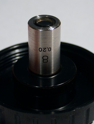
The NA value is printed on microscope objectives (e.g., 40×/0.65, 100×/1.4 Oil). It is not a measure of magnification but of light-gathering and resolution capability. While magnification changes how large features appear, NA determines how much fine detail can be resolved. This distinction recurs throughout this article; for more on this, see Common Misconceptions About NA and Magnification.
Numerical aperture is central to almost every performance aspect of a microscope, influencing lateral resolution, axial resolution, contrast, brightness, and practical workflows. It also dictates how to set up the illumination system; for instance, the condenser’s NA must be considered for brightfield resolution and contrast, as discussed in Optimizing Condenser NA and Alignment for Resolution.
How Numerical Aperture Governs Lateral and Axial Resolution
Resolution is the ability to distinguish neighboring features as separate. In light microscopy, diffraction by the lens aperture and the wave nature of light impose a fundamental limit on resolution. Numerical aperture is the parameter that directly ties the lens geometry and the medium to that diffraction limit.
Lateral resolution: Rayleigh and Abbe perspectives
Two commonly cited criteria quantify lateral (in-plane) resolution:
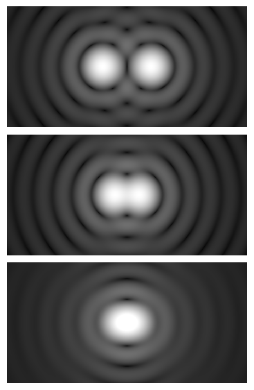
- Rayleigh criterion (incoherent imaging): For isolatable point sources or non-periodic features under incoherent conditions (e.g., fluorescence), the minimum resolvable center-to-center separation
dis approximately:d ≈ 0.61 · λ / NA
whereλis the relevant wavelength (emission wavelength for fluorescence; detection wavelength for reflected/scattered light). This expression uses the objective’s NA. - Abbe diffraction limit (periodic structures in transmitted light): For periodic structures (e.g., line gratings) under transmitted brightfield with a condenser, resolution depends on both the objective and the condenser NA:
d ≈ λ / (NA_obj + NA_cond)
When the condenser NA is matched to the objective NA (a common practice for high-resolution brightfield), this simplifies tod ≈ λ / (2 · NA_obj). This is consistent with Abbe’s classic result for resolving line pairs when the 0th and first diffracted orders are captured.
Attribution: Spencer Bliven
These two formulas answer slightly different questions. The Rayleigh expression emphasizes the point-spread function and is widely used for fluorescence microscopy and incoherent imaging. The Abbe formulation explicitly includes the condenser and is especially relevant to high-contrast resolution of periodic detail in transmitted light. For practical purposes, many microscopists remember both and choose the one that matches the imaging mode and specimen structure. For a deeper look at the condenser’s role, see NA, Contrast, and Illumination Coherence and Optimizing Condenser NA and Alignment.
Axial resolution and sectioning
Axial (out-of-plane) resolution refers to how well features separated along the optical axis can be distinguished. In widefield imaging, a commonly used approximate relation for incoherent light is:
Δz ≈ 2 · n · λ / NA²
Here, n is the refractive index of the immersion medium and λ is the detected wavelength. The key scaling is inverse with NA squared, indicating that axial resolution improves very rapidly as NA increases. In fluorescence confocal microscopy (which uses a pinhole to reject out-of-focus light), the axial resolution can be improved relative to widefield under similar NA and wavelength; however, the exact constants depend on pinhole size and system specifics, so we emphasize the trend rather than a single universal formula.

Dimensions
XY: 4096×4096 px (167.92×167.92 µm)
Z: 103 slices (8.56 µm) (merged into a single slice)
Scanner Settings
ScanMode: xyz
Pinhole [m]: 95.5 µm
Pinhole [airy]: 1.00
Total Size-Width: 167.9 µm
Total Size-Height: 167.9 µm
Total Size-Depth: 8.6 µm
StepSize: 0.08 µm
Voxel-Width: 41.0 nm (pixel size)
Voxel-Height: 41.0 nm (pixel size)
Voxel-Depth: 83.9 nm
Voxel-Volume: 141035.9 nm³
Zoom: 1.5
Objective: HCX PL APO CS 63.0×1.40 OIL UV
Numerical aperture: 1.40
Attribution: Howard Vindin
Airy patterns, point spread, and OTF/MTF
When a diffraction-limited objective images a point emitter, the image is not a point; it is a concentric diffraction pattern called the Airy pattern. The central bright disk’s diameter (to first minimum) is roughly:
Airy disk diameter ≈ 2 · 1.22 · λ · f/# ≈ 1.22 · λ / NA (at the object plane)
Several equivalent forms exist; the important takeaway is how the Airy disk scales inversely with NA. In the frequency domain, higher NA extends the cutoff spatial frequency of the optical transfer function (OTF), meaning finer detail is transmitted. Because the mathematics can be abstract, many learners start by internalizing the simple scaling rules: lateral resolution ~ 1/NA, axial resolution ~ 1/NA².
NA, Contrast, and Illumination Coherence
Contrast is the other half of the visibility equation. Even if two features are smaller than the theoretical resolution limit, if they differ strongly in intensity, they may appear distinct. Conversely, features larger than the theoretical limit can be hard to see if contrast is poor. Numerical aperture interacts with illumination coherence to shape contrast and practical resolution.
Condenser NA and brightfield contrast
In transmitted brightfield, the condenser forms and controls the illumination cone. A good rule of thumb:
- To approach the best periodic detail resolution, set condenser NA to approximately match the objective’s NA, so that diffracted orders needed for Abbe resolution are present. This is consistent with the Abbe formulation.
- If contrast is too low or the sample is thick and scattering, reducing the condenser NA can increase contrast (by increasing coherence and narrowing the illumination cone), at the expense of highest spatial frequency transfer.
These are conceptual guidelines, not step-by-step instructions. The precise setting depends on sample transparency, staining, and thickness. In all cases, proper alignment of the illumination optics is necessary to realize the expected behavior; for context, see Optimizing Condenser NA and Alignment for Resolution.
Coherence considerations
Coherence refers to the degree to which light waves maintain a fixed phase relationship. Highly coherent light (e.g., laser illumination) can produce strong interference effects and speckle, which alter contrast and can degrade image quality in brightfield. In contrast, partially coherent illumination (as in Köhler illumination with a finite condenser aperture) balances contrast and resolution. Key points:
- Incoherent imaging (e.g., fluorescence) is governed by the Rayleigh-type expressions that depend primarily on objective NA and emission wavelength.
- Partially coherent transmitted brightfield is where condenser and objective NA both matter for resolving periodic features as per Abbe’s formula.
- Coherent illumination (e.g., laser brightfield) typically yields poorer resolution limits for isolated features (e.g., ~0.82·λ/NA) and introduces speckle and interference artifacts unless mitigated.
Contrast mechanisms that modify the phase of light—such as phase contrast and differential interference contrast (DIC)—leverage controlled coherence and specialized optics to convert phase variations into intensity differences. While those techniques are beyond the scope of this fundamentals article, it is helpful to remember that their performance envelopes also track with NA: higher NA increases potential resolution but reduces depth of field.
Refractive Index, Immersion Media, and Wavelength Dependence
The immersion medium directly multiplies sin(θ) in the NA formula. This seemingly simple factor has deep implications for resolution, aberrations, and optical throughput.
Air, water, glycerol, and oil immersion
- Air (n ≈ 1.00): Easy to use, no liquid handling, but limits NA to ≲0.95 for dry objectives because
sin(θ) ≤ 1. - Water (n ≈ 1.33): Better index match to aqueous samples and reduces spherical aberration when imaging into water-based media. Allows high-NA objectives (e.g., ~1.0–1.2).
- Glycerol (n ≈ 1.47): An intermediate index useful for samples mounted in higher-index media.
- Oil (n ≈ 1.515, typical standard immersion oil): Enables the highest NA values in conventional objectives (e.g., up to ~1.4). Often used for high-resolution imaging at or near the cover glass interface.

Attribution: Trondarne
Choosing the immersion medium is not just about maximizing NA. It is about matching the optical path between the cover glass, mounting medium, and specimen to reduce aberrations. A mismatch between the design conditions of the objective (cover glass thickness, refractive indices) and the actual sample can severely degrade effective resolution, even if the nominal NA is high. See Trade-offs: Working Distance, Depth of Field, and Field Flatness for more on how such mismatches manifest.
Cover glass thickness and correction collars
Many high-NA objectives are designed to be used with a specific cover glass thickness (commonly 0.17 mm, often referred to as #1.5). Deviations introduce spherical aberration. Some objectives include a correction collar that allows fine adjustment to compensate for slight variations in cover glass or sample mounting. When using such an objective, optimizing the correction collar can reduce blur and restore contrast, effectively recovering the resolution expected from the stated NA.
Wavelength scaling and color effects
Resolution scales with wavelength: shorter wavelengths resolve finer details. In white-light brightfield, the effective resolution is influenced by the spectral sensitivity of the detector and the spectral content reaching the objective. In fluorescence, using the emission wavelength in calculations is appropriate because that is the light forming the image. Achromat, fluorite, and apochromat objectives are corrected to varying degrees for chromatic aberration; better correction improves focus consistency across colors but does not change the fundamental NA-limited cutoff, which still scales inversely with wavelength.
Trade-offs: Working Distance, Depth of Field, and Field Flatness
High NA brings benefits and constraints. Understanding these trade-offs helps you choose the right objective for a given specimen and imaging task.
Working distance and clearance
Working distance is the distance from the objective’s front lens to the focused specimen plane. As NA increases, the front lens typically must be larger and closer to the sample to accept a wider cone of rays. Consequently, high-NA objectives often have short working distances. This can complicate imaging of thick or uneven specimens and increases the risk of contact with the cover glass. Long working distance (LWD) objectives sacrifice NA to provide more clearance; they are invaluable for bulky specimens or micro-manipulation tasks where space is needed around the sample.
Depth of field and sectioning
Depth of field (DOF) is the axial range over which the image appears acceptably sharp. At diffraction-limited focus, a widely used scaling is:
DOF ∝ n · λ / NA²
While exact DOF depends on criteria and detection geometry, the most important intuition is the inverse square relationship with NA. Doubling NA roughly quarters the DOF. This is great for optical sectioning but can make focusing more demanding. In thick samples, a shallow DOF can increase apparent contrast by rejecting out-of-focus blur, but it also risks excluding relevant structures outside the focal plane. This interplay shows up again in Choosing Objective NA for Different Samples.
Field flatness and plan correction
Field curvature is an aberration where the best focus lies on a curved surface rather than a plane. “Plan” objectives are corrected to deliver a flatter field across the specified image area. High-NA plan-apochromats provide both high resolution and well-corrected fields, but they can be more demanding in terms of sample preparation (e.g., cover glass quality) and illumination. If you observe sharp focus at the center but softness at the edges, insufficient field flatness or misalignment could be at play rather than a limitation of NA per se.
Signal, brightness, and photophysics
Higher NA increases light collection efficiency, improving signal-to-noise ratio for a given illumination exposure. In fluorescence, this is favorable for detecting faint emitters. However, higher excitation intensities or prolonged exposures can cause photobleaching and, in live samples, phototoxic effects. Balancing NA, exposure, and imaging modality is part of practical optimization rather than a single theoretical optimum. Even in non-fluorescent imaging, very high NA can reveal ultra-fine detail that may not be necessary for a given task and can complicate focusing and alignment.
Choosing Objective NA for Different Samples and Modalities
Selecting an objective’s NA is less about picking the “biggest number” and more about balancing resolution, DOF, working distance, sample properties, and contrast mechanism. Below are scenario-driven considerations. As you read, note the cross-references to earlier concepts like resolution formulas and trade-offs.
Thin, fixed transparent samples in brightfield
- Goal: Resolve fine structure (e.g., line gratings, cell walls in thin sections).
- Guidance: A higher NA dry objective (e.g., 0.65–0.95) or oil immersion if the specimen is well-mounted under a suitable cover glass can yield excellent detail.
- Condenser: Match condenser NA to objective NA to approach Abbe’s
λ / (NA_obj + NA_cond)limit; see condenser optimization.
Live cells in aqueous media (phase contrast or DIC)
- Goal: Enhance contrast of transparent structures while keeping cells viable.
- Guidance: Water immersion objectives help reduce spherical aberration when focusing into aqueous media. Moderate to high NA (~0.8–1.2) improves resolution and contrast in DIC/phase but shortens DOF.
- Considerations: Avoiding refractive index mismatches is important to maintain image quality; align contrast optics appropriately for the chosen NA.
Fluorescence imaging of thin specimens
- Goal: Maximize detection of emitted light and resolve small features.
- Guidance: Higher NA directly increases photon collection and improves lateral and axial resolution via the Rayleigh relation
d ≈ 0.61·λ/NAandΔz ≈ 2·n·λ/NA². - Note: For thick fluorescent specimens, axial blur in widefield increases; consider optical sectioning strategies. The fundamental NA scaling remains valid for the diffraction-limited PSF.
Reflective or high-index samples in reflected-light (epi) mode
- Goal: Surface detail, microstructure, or metallographic features.
- Guidance: High NA objectives improve lateral resolution. Because illumination and detection share the objective, condenser NA is not separately adjusted; contrast depends on surface reflectivity, polarization, and illumination aperture settings.
Thick or uneven specimens
- Goal: Survey large depth ranges or maintain clearance over structures.
- Guidance: A lower NA, long-working-distance objective may be preferable. Though the theoretical resolution is reduced, the increased DOF and working distance can make imaging practical and informative.
Attribution: Trondarne
Darkfield and oblique illumination
- Goal: Visualize edges and small scatterers with enhanced contrast.
- Guidance: In transmitted darkfield, the condenser delivers a hollow cone that bypasses the objective’s front aperture; typically, the condenser NA must exceed the objective NA so that only scattered light enters the objective. The objective’s NA still governs resolving power of the scattered signal.
Optimizing Condenser NA and Alignment for Resolution

Attribution: ZEISS Microscopy from Germany
In transmitted brightfield, the condenser is as important as the objective for forming high-quality images. Its NA sets the angular spread of illumination, which in turn determines which diffracted orders are present at the sample and how they are captured by the objective. Conceptual guidelines include:
- Match NA for highest periodic detail: Setting
NA_cond ≈ NA_objtends to maximize the transfer of high spatial frequencies for periodic structures (Abbe condition). This is most beneficial for thin, well-prepared samples with good intrinsic contrast or staining. - Reduce NA to gain contrast in low-contrast specimens: Stopping down
NA_condincreases partial coherence and directional illumination, often increasing edge contrast while sacrificing ultimate resolution. This is useful for thick, weakly absorbing samples. - Uniform field illumination matters: Even with ideal NA, off-axis or non-uniform illumination can compromise effective resolution and introduce artifacts. Ensuring that the source is properly imaged into the back focal plane of the objective (as in standard Köhler alignment) helps maintain the assumptions underlying the resolution formulas.
These points summarize the role of the condenser NA without prescribing step-by-step procedures. In practice, careful adjustments, stable mounting media, and appropriate cover glass selection are necessary to realize the theoretical benefits that NA enables.
Back-of-the-Envelope Examples and Sanity Checks
Order-of-magnitude calculations solidify intuition. The numbers below assume common wavelengths and typical NA values. They are approximate and intended for educational insight.
Example 1: Lateral resolution in fluorescence
Suppose you image green fluorescence with an emission peak around λ = 550 nm using two different objectives. Using the Rayleigh-type criterion d ≈ 0.61·λ/NA:
- NA = 0.65 (dry objective):
d ≈ 0.61 · 550 nm / 0.65 ≈ 516 nm(about 0.52 μm). - NA = 1.40 (oil immersion):
d ≈ 0.61 · 550 nm / 1.40 ≈ 240 nm(about 0.24 μm).
Doubling NA more than halves the lateral minimum resolvable distance. This makes clear why high-NA oil objectives are preferred for resolving submicron features in fluorescence.
Example 2: Axial resolution in widefield
Using Δz ≈ 2·n·λ/NA² with λ = 550 nm and immersion index n matching the objective type:
- NA = 0.65 (air, n ≈ 1.00):
Δz ≈ 2 · 1.00 · 550 nm / (0.65)² ≈ 2,600 nm(about 2.6 μm). - NA = 1.40 (oil, n ≈ 1.515):
Δz ≈ 2 · 1.515 · 550 nm / (1.40)² ≈ 850 nm(about 0.85 μm).
Axial resolution improves even more dramatically with NA due to the square in the denominator.
Example 3: Abbe limit with matched condenser
In transmitted brightfield of a periodic grating, with NA_cond ≈ NA_obj = 0.95 and λ = 550 nm:
d ≈ λ / (NA_obj + NA_cond) ≈ 550 nm / (0.95 + 0.95) ≈ 289 nm
Again, the numbers underscore how matched condenser and objective NA can help transmit higher spatial frequencies for periodic structures, consistent with Abbe’s treatment.
Example 4: Depth of field trend
If you keep all else equal and move from NA 0.50 to NA 1.0, the DOF scales approximately with 1/NA², so the DOF shrinks by about a factor of four. This makes focusing more sensitive and can help with optical sectioning in thin specimens but complicates work with thick, uneven samples.
Note: These formulas capture the dominant scaling with NA and λ. Exact numeric factors depend on definitions, imaging geometry, and contrast mechanism. For instance, coherent illumination has different constants than partially or fully incoherent illumination. Nevertheless, the inverse dependence on NA—and NA² for axial behavior—is broadly robust.
Common Misconceptions About NA and Magnification
Because NA and magnification often appear together on objective barrels, it is easy to conflate them. Clarifying a few misconceptions can prevent wasted effort and guide better choices.
- “More magnification means more resolution.” Not necessarily. Magnification enlarges the image, but resolution depends on NA and wavelength. An over-magnified, low-NA image simply spreads the same detail over more pixels without revealing new information (so-called empty magnification).
- “High NA always gives better images.” Higher NA offers finer resolution and greater light collection, but it also reduces DOF, shortens working distance, and can increase sensitivity to sample preparation errors (e.g., cover glass thickness). For thick or rough specimens, a slightly lower NA may yield clearer, more interpretable images.
- “Condenser settings don’t affect resolution.” In transmitted brightfield, the condenser NA directly influences resolution of periodic structures and overall contrast, per Abbe’s criterion. Neglecting the condenser often leaves resolution on the table.
- “Immersion medium doesn’t matter if the NA is high.” It does. Mismatches between immersion medium, cover glass, and sample refractive indices introduce aberrations that can erase the theoretical advantage of a high NA. Correct match and proper use of correction collars are essential when applicable.
- “Resolution claims are universal.” Formulas quoted without context can mislead. Know whether the limit applies to incoherent fluorescence, partially coherent brightfield, or coherent illumination, and whether condenser NA is included.
Frequently Asked Questions
Does a higher NA always improve low-light performance?
Higher NA increases the solid angle of light collection, which can improve signal levels for a given illumination dose. In fluorescence, this directly benefits detection efficiency. However, practical performance also depends on sample brightness, optical losses, and noise in the detection chain. Furthermore, higher NA reduces DOF and working distance, which may complicate focusing and alignment. If you are operating near the noise floor, higher NA is usually helpful, but ensure that sample preparation and optical matching are optimized to avoid aberrations that negate the benefit.
How should I think about NA when planning multicolor fluorescence?
Use the emission wavelength for each channel to estimate resolution via d ≈ 0.61·λ/NA. Shorter-wavelength channels will have slightly better theoretical resolution than longer-wavelength channels with the same NA. If registration across colors is important, select objectives with good chromatic correction and maintain consistent immersion conditions. The NA-limited cutoff still applies individually to each emission band; interpret fine features across channels with the respective resolution limits in mind.
Final Thoughts on Mastering Numerical Aperture and Resolution
Numerical aperture is the lever that couples the physics of diffraction with the practical craft of microscopy. It sets the scale for what you can resolve laterally and axially; it shapes contrast through illumination geometry and coherence; and it influences working distance and depth of field in ways that directly affect day-to-day imaging. A few high-level takeaways:
- Match NA to the task: Choose the lowest NA that still resolves the features you care about, especially when working distance, DOF, or sample thickness is limiting.
- Mind the medium: Align immersion medium, cover glass, and mounting medium with the objective’s design to prevent aberrations that mask the benefits of high NA.
- Use the condenser strategically: In transmitted brightfield, set condenser NA with intention—match for maximum periodic detail transfer or reduce for added contrast, as the specimen demands.
- Remember the scaling: Lateral resolution tends to improve proportionally to 1/NA; axial resolution and DOF vary roughly as 1/NA². Small increases in NA can yield big benefits in sectioning.
Armed with these principles, you can interpret objective markings with confidence, predict the impact of a change in immersion or wavelength, and make deliberate choices that elevate image quality. If you enjoyed this deep dive and want more technically rigorous, accessible explanations of microscopy, consider subscribing to our newsletter to be notified of future installments and related topics. You can also revisit specific sections—such as resolution theory, immersion media, or condenser strategy—whenever you need a quick refresher.


