
Table of Contents
- What Are Phase Contrast and DIC Microscopy?
- Optical Principles: From Phase Objects to Image Contrast
- Anatomy of a Phase Contrast System
- Anatomy of a Differential Interference Contrast (DIC) System
- Image Characteristics, Artifacts, and Interpretation
- Performance Trade-offs: Resolution, NA, and Illumination
- Choosing Between Phase Contrast and DIC for Common Specimens
- Setup, Alignment, and Compatibility Considerations
- Quantitative Imaging Notes: What You Can and Can’t Measure
- Frequently Asked Questions
- Final Thoughts on Choosing the Right Contrast Method
What Are Phase Contrast and DIC Microscopy?
Many biological and soft-matter specimens are nearly transparent under brightfield illumination. Their refractive index is close to that of the surrounding medium, so they contribute little to intensity contrast even though they alter the phase of transmitted light. Phase contrast microscopy and Differential Interference Contrast (DIC) microscopy are two widely used techniques that convert these otherwise invisible phase variations into intensity differences you can see and record.
Both methods target the same challenge—visualizing unstained, low-absorption samples such as live cells, thin tissues, protists, and microfluidic structures—yet they operate on different optical principles and produce characteristically different images. Understanding these differences helps you choose the right contrast method for your specimen and your measurement goals.

Artist: ArkhipovSergey
- Phase contrast converts small phase shifts into intensity primarily by interfering diffracted light from the specimen with attenuated, phase-shifted background light (the undiffracted or low-angle components). It excels at highlighting transparent structures but is prone to halos around high-contrast boundaries.
- DIC (Nomarski DIC) uses polarization optics and beam shearing interferometry to translate gradients of optical path length (OPL) into intensity. It tends to deliver crisp, pseudo-relief images with edge emphasis and fewer halos, but requires specialized, matched components and is sensitive to birefringence in the optical path.
In this article, we compare their optics, components, and image characteristics, discuss practical trade-offs in numerical aperture (NA), resolution, and light throughput, and offer decision criteria for typical specimens. If you are scanning for specific topics—artifacts or alignment, for example—jump ahead to Image Characteristics, Artifacts, and Interpretation or Setup, Alignment, and Compatibility Considerations.
Optical Principles: From Phase Objects to Image Contrast
Understanding phase contrast and DIC begins with the concept of a phase object. A transparent specimen with spatially varying refractive index n(x, y, z) alters the phase of transmitted light, but often only weakly affects amplitude. The optical path length through the object is proportional to the integral of refractive index along the optical axis. The spatial variation in optical path length produces a phase delay relative to light passing only through the surrounding medium.
For transmitted light microscopy at wavelength λ, the phase shift φ(x, y) at a point (x, y) is commonly expressed (qualitatively) as being proportional to the optical path difference (OPD) between the specimen and the reference medium. Weak phase objects (small phase shifts and negligible absorption) are abundant in biology. Unmodified brightfield imaging of such objects can yield low contrast, because intensity is mainly sensitive to amplitude, not phase.
Phase Contrast: Interfering Background and Diffracted Light
Phase contrast microscopy, introduced by Frits Zernike, implements a spatial filter at the objective’s rear focal plane to manipulate the background (undiffracted/low-angle) light differently than the diffracted light from the specimen. A ring-shaped condenser annulus produces a hollow cone of illumination. At the objective’s back focal plane, a corresponding phase plate contains a ring that imparts a phase shift—commonly one-quarter wavelength (90°)—to the background light and often attenuates its amplitude. The diffracted components, distributed away from the ring, remain mostly unmodified. When these two components interfere at the image plane, the result is intensity contrast proportional, under weak-phase conditions, to the specimen’s phase variations.

Artist: Egelberg
This transformation is not uniform across all spatial frequencies, and it comes with a trade-off: the ring-shaped filter alters the microscope’s contrast transfer function and can introduce characteristic halos and shade-off artifacts. Nevertheless, phase contrast remains a staple for live-cell viewing due to its simplicity and effectiveness in revealing transparent structures.
DIC: Beam Shearing Interferometry and Gradient Contrast
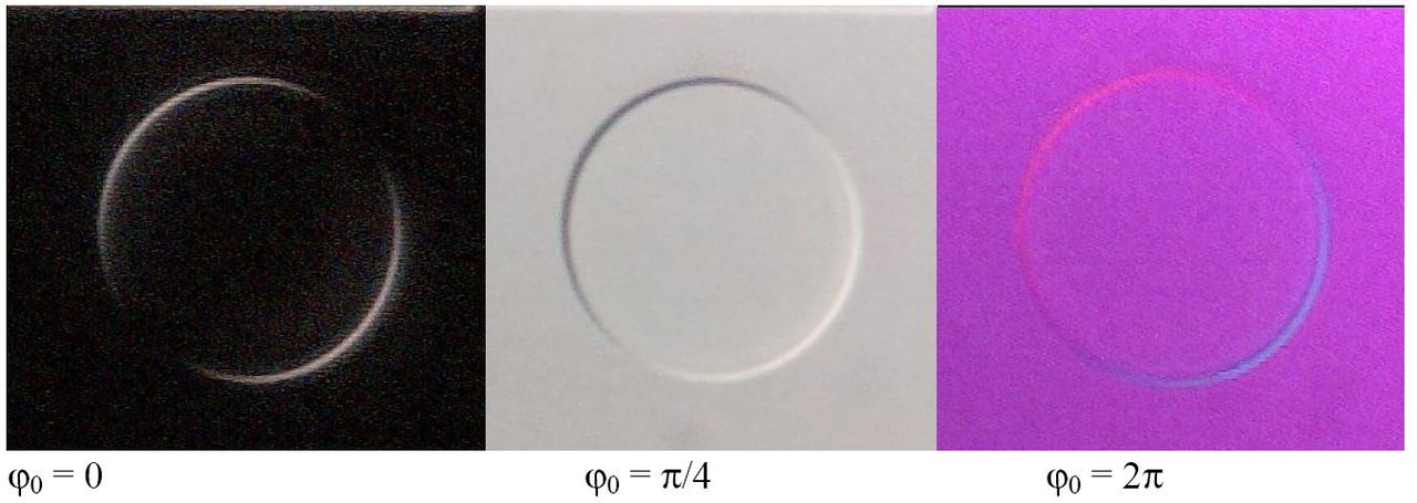
DIC microscopy uses polarization optics—often a pair of Wollaston or Nomarski prisms—to split the illumination into two laterally displaced, orthogonally polarized beams that pass through adjacent regions of the specimen separated by a small shear distance. After traversing the sample, these beams are recombined with a controlled bias retardation, producing interference whose intensity depends on the phase difference between the two adjacent sampling points. The key effect is that the recorded intensity is related to the spatial derivative (gradient) of the optical path length along the shear direction.
Artist: Wolftrans
Because DIC emphasizes gradients, uniform regions appear with little signal, while edges and slopes display strong contrast with a pseudo-3D, “shadow-cast” appearance. The final look depends on the shear orientation and the selected bias. DIC requires a polarizer, analyzer, and strain-free optical components, as well as prisms and objectives matched for DIC operation. It is especially valued when you need crisp edge definition without the halos typical of phase contrast, though it is sensitive to unwanted birefringence in the optical train.
In short, phase contrast transforms local phase into intensity, whereas DIC transforms the gradient of phase into intensity. This distinction underpins their different image appearance and measurement behavior. We will revisit the implications for interpretation in Quantitative Imaging Notes.
Anatomy of a Phase Contrast System
A phase contrast microscope builds on a standard transmitted-light stand with a few critical additions and matched components. The goal is to ensure that the ring of illumination created in the condenser aligns precisely with the phase ring at the objective’s back focal plane.
Condenser Annuli and Phase Turrets
- Condenser annulus: A ring-shaped aperture placed at the front focal plane of the condenser creates a hollow cone (“ring”) of illumination. Many condensers include a turret with multiple annuli (e.g., Ph1, Ph2, Ph3) matched to different objective magnifications/NA.
- Matching matters: Each annulus is designed to pair with a specific phase objective containing a phase ring of the corresponding size. Mismatched rings degrade contrast and can introduce asymmetries or odd artifacts.
Phase Objectives and Phase Plates
- Phase objective: Externally similar to ordinary objectives but internally equipped with a phase plate holding the phase ring at the back focal plane. The ring shifts the phase of the undiffracted/low-angle light (typically by 90°) and may attenuate it to balance intensities for effective interference.
- Transmission and effective NA: The phase ring blocks or attenuates some of the background light and alters the pupil function. Although the theoretical resolution limit remains governed by the objective’s NA and the illumination NA, the contrast transfer at certain spatial frequencies changes. This can slightly reduce perceived fine-detail visibility compared to the same objective in brightfield.
Ring Alignment and Centering
For optimal contrast, the condenser annulus must be accurately centered relative to the objective’s phase ring. Many systems include telescopes or centering tools for visualizing the back focal plane and aligning the rings. Misalignment reduces image contrast and can generate nonuniform shading. While alignment steps are straightforward in principle, precise centering is essential and is discussed in relation to image quality in Setup, Alignment, and Compatibility Considerations.
Illumination Considerations
- Uniform field: Phase contrast benefits from a uniform, well-filled illumination ring. Nonuniform or off-center illumination can mimic specimen gradients or produce bright/dim lobes.
- Specimen thickness: Best results typically occur for thin, weakly scattering specimens. Thick or highly refractile samples can generate stronger diffracted components, accentuating halos and shade-off.
Because phase contrast relies on the interference between background and diffracted light, any factor that changes the balance between these components—aperture adjustment, ring attenuation, or refractive index mismatch—will influence contrast and artifact strength. These trade-offs are summarized later under Performance Trade-offs.
Anatomy of a Differential Interference Contrast (DIC) System
DIC microscopy requires polarization optics integrated into the illumination and detection paths. Incremental adjustments in bias and shear direction give the user control over image appearance, but require appropriate matching of components.
Key Optical Elements
- Polarizer: Produces linearly polarized illumination entering the specimen. Placement is typically before the condenser optics so that the prism can split the beam.
- First prism (shear): A Wollaston or Nomarski prism in the condenser or objective path splits the beam into two orthogonally polarized components that are laterally displaced by a small amount (shear). The spacing is typically a small fraction of the field resolution so that adjacent sample regions are probed.
- Second prism (recombination): Another prism downstream recombines the beams. The relative phase between the beams encodes the difference in optical path length between the two sample points.
- Analyzer: A second linear polarizer (oriented relative to the first) converts the optical phase difference into measurable intensity variations.
- Bias retardation: DIC systems allow adjusting a fixed phase offset between beams. Appropriate bias selection can linearize response for weak gradients and optimize contrast; changing bias also affects the brightness and \”shadow\” direction perceived in the image.
Objective Compatibility and Prism Matching
- DIC-capable objectives: DIC typically requires objectives designed for strain-free performance and matched to specific prisms labeled by magnification or an index. Using an objective with the wrong prism can compromise shear, contrast, or uniformity.
- Strain-free optics: Birefringence in lenses, filters, or even mechanical stress in glass elements introduces unwanted phase shifts for polarized beams, degrading image quality and creating color or intensity nonuniformities.
- Shear direction: Many DIC systems let you rotate the shear direction. Features aligned parallel to the shear can appear with minimal contrast, whereas features crossed by the shear direction show strong gradients. This directional sensitivity underpins the technique’s edge emphasis and pseudo-relief rendering.
Light Budget
Polarizers and prisms reduce light throughput compared to brightfield. As a rule of thumb, expect to use brighter illumination or longer exposures than you would in phase contrast for similar signal levels, especially at high NA. This has implications for live imaging and high-speed capture discussed in Performance Trade-offs.
Image Characteristics, Artifacts, and Interpretation
Comparing images from phase contrast and DIC reveals immediately recognizable differences. These differences matter, not just for aesthetics, but for scientific interpretation.
Phase Contrast: Halos and Shade-Off

Artist: Pilarbini
- Halos: Bright or dark fringes at boundaries arise from the spatial filtering built into the phase plate and the ring illumination. They are not physical halos in the sample but optical artifacts. Halos tend to exaggerate edges and can obscure nearby fine detail.
- Shade-off: Slowly varying regions may appear overly dim or bright depending on local phase relative to the background reference. This unevenness can complicate quantitative interpretation of absolute optical path length.
- Contrast sign: By design, phase plates can be configured to yield positive or negative contrast (e.g., structures of higher refractive index appear darker or brighter). Modern systems often default to positive contrast but the principle remains—contrast sign relates to the chosen phase shift and attenuation.
- Edge emphasis: While halos are artifacts, the technique’s sensitivity to boundaries helps reveal cellular membranes, vacuoles, and organelle outlines rapidly.
DIC: Pseudo-Relief and Directional Gradients
Artist: Adn25fr
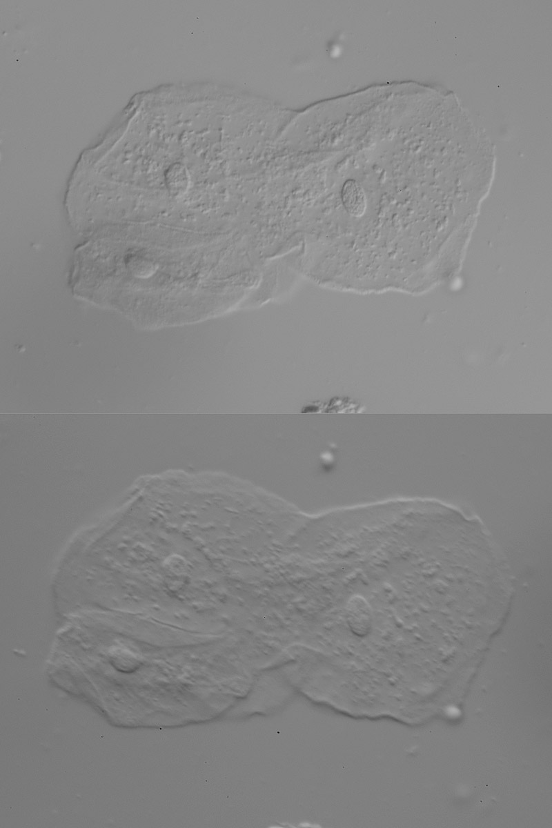
- Pseudo-3D appearance: DIC images appear embossed because intensity encodes the gradient of optical path length along the shear direction. A sloped phase profile generates brightening on one side and darkening on the other, mimicking lighted relief.
- Directional dependence: Features aligned parallel to the shear direction may produce minimal contrast, while perpendicular features show strong contrast. Rotating the shear or the sample can alter apparent visibility of structures.
- Reduced halo: Compared to phase contrast, DIC generally exhibits fewer halos around edges. Fine structures often appear cleaner, making DIC preferred for certain live-cell observations and thin polymer structures.
- Color fringes (white light): With broadband illumination, residual wavelength dependence in retardation can produce subtle color shifts in DIC images. These are not staining artifacts but optical interference effects. Systems designed for near-achromatic DIC minimize these shifts.
Brightfield Baseline
For context, brightfield images of the same specimens may be low contrast without staining. Brightfield contrast derives mostly from absorption and scattering amplitude differences. For transparent, weakly scattering samples, brightfield tends to undershoot details that phase contrast and DIC reveal. This baseline helps evaluate the added value and the artifacts introduced by each technique.
Importantly, neither phase contrast nor DIC produces a direct map of thickness or refractive index; each applies a transformation that depends on the optical configuration. The implications for measurement are explored in Quantitative Imaging Notes.
Performance Trade-offs: Resolution, NA, and Illumination
Both techniques operate within the physical limits set by wavelength and numerical aperture. However, the added optical elements and pupil filtering change contrast transfer and light throughput, which can affect the visibility of fine detail in practice.
Resolution and Numerical Aperture
- Abbe limit: Lateral resolution in transmitted light microscopy is commonly estimated using the Abbe criterion
d ≈ 0.61 × λ / NA, where NA is the numerical aperture of the imaging system. Increasing NA (objective and condenser) improves spatial resolution. - Phase contrast pupil modification: The phase ring modifies the pupil function by attenuating and phase-shifting components near the optical axis. While the theoretical cutoff spatial frequency is still governed by NA, the contrast for certain spatial frequencies can be reduced, making some high-frequency details less pronounced than with a comparable brightfield objective of the same NA.
- DIC and high NA: DIC performance benefits from high NA objectives and condensers because the technique relies on interference between closely spaced sampling points. High NA improves sensitivity to subtle gradients. However, the system’s shear, bias, and polarization optics must be well matched to maintain uniform contrast across the field.
Light Throughput and Exposure
- Polarization losses in DIC: Polarizers transmit only one polarization state. With unpolarized illumination, initial transmission is typically about half the input intensity through a perfect linear polarizer. Additional optical elements introduce further loss. In practice, DIC often requires brighter illumination or longer exposures than phase contrast.
- Phase ring attenuation: Phase contrast attenuates the background (undiffracted) component to balance interference with diffracted light. This reduces total transmitted intensity compared to brightfield. Nonetheless, the net light budget is often more favorable than DIC for equivalent visibility, especially at moderate NA.
- Signal-to-noise considerations: More complex optical trains can amplify sensitivity to stray reflections, scattering, or detector noise at low light levels. Careful control of stray light and stable illumination benefits both methods.
Depth of Field and Optical Sectioning Feel
- Phase contrast: Depth cues are limited; out-of-focus features can still contribute halos and background structure. Adjusting aperture can influence the trade-off between contrast and depth of field.
- DIC: The gradient-based contrast and directional shear can give an “optical sectioning” feel by emphasizing local slopes, but DIC is not a true optical sectioning method. Defocus changes the apparent relief and can mislead interpretation of axial positions.
When comparing visibility of subcellular structures or microfabricated features, consider not only the nominal NA but also how each technique’s contrast transfer behaves for the spatial frequencies of interest, and how much light you can devote to exposure without compromising the specimen.
Choosing Between Phase Contrast and DIC for Common Specimens
Selecting the right technique depends on specimen properties (thickness, refractive index variations, birefringence), objectives and condensers available, and your imaging goals (qualitative observation, tracking, or quantitative analysis). The following scenarios illustrate typical choices.
Live Adherent Cells in Culture
- Phase contrast: Excellent general-purpose choice for rapid inspection of cell morphology, confluence, and motility. Membrane outlines, nuclei, and vesicles stand out quickly. Halos can exaggerate boundaries or obscure nearby features.
- DIC: Provides crisper edges with reduced halos and pleasant pseudo-relief of cytoskeletal features. Directional sensitivity can underrepresent structures aligned with the shear. Requires compatible plates and optics; see Setup, Alignment, and Compatibility regarding plasticware.
Suspension Cells and Protozoa
- Phase contrast: Strong visibility of floating cells, flagella beating, and internal vacuoles, with caveat of halos near high-index boundaries.
- DIC: Excellent for edge detail and motility tracking; choose shear to maximize contrast of features of interest.
Microorganisms in Natural Water Samples

Artist: Danja Currie-Olsen & Brian S. Leander
- Phase contrast: Reveals internal structures of algae and protists effectively; halos can make dense fields visually busy.
- DIC: Enhances edges and surface textures, helpful for identifying morphology. Be mindful of birefringent particles that can introduce color fringes.
Thin Polymer Films and Microfabricated Channels
- Phase contrast: Useful for quick inspection of channel boundaries and defects; halos may mask close-spaced lines.
- DIC: Highlights edges and topography-like gradients along shear; can be excellent for micrometric relief features. Directionality matters—rotate shear to probe different edges.
Birefringent or Crystalline Specimens
- Phase contrast: Generally unaffected by specimen birefringence in the same way DIC is; suitable for many thin crystalline or fibrous samples where halos are tolerable.
- DIC: Because DIC relies on polarization, inherent birefringence in the specimen can interact with the optics to produce strong, sometimes colorful artifacts. Evaluate carefully; in some cases, polarized light microscopy (a different technique) may be preferable to intentionally leverage birefringence.
Thicker Biological Sections
- Phase contrast: Out-of-focus structure can reduce clarity and produce halos extending from planes above and below focus.
- DIC: Provides strong edge emphasis but can also show misleading relief cues when structures span multiple depths. Neither method replaces true optical sectioning modalities for thick samples.
In many labs, both techniques coexist. When you can switch modes, a practical workflow is to scan in phase contrast for quick overview, then switch to DIC to inspect edges and textures with fewer halos. Alternatively, if your sample sits in plasticware or exhibits birefringence, phase contrast may be the more consistent choice. To understand compatibility constraints, read Setup, Alignment, and Compatibility Considerations.
Setup, Alignment, and Compatibility Considerations
Both phase contrast and DIC depend on careful matching and alignment of optical components. While this section avoids procedural detail, it highlights the dependencies that influence whether a given configuration will deliver the expected image quality.
Phase Contrast Matching and Centering
- Annulus–ring matching: Confirm that the condenser annulus designation (e.g., Ph1/Ph2) matches the objective’s phase ring. Mismatches reduce contrast.
- Back focal plane centering: The annulus must be concentric with the objective’s phase ring. Even small offsets degrade uniformity and create uneven halos. Many systems include centering screws for this purpose.
- Illumination aperture: Adjusting the condenser aperture changes the balance between resolution, contrast, and depth of field. Too narrow an aperture inflates halos and sacrifices resolution; too wide reduces contrast.
DIC Component Compatibility
- Polarizer and analyzer orientation: These must be aligned to the DIC prisms’ specifications. Misorientation reduces interferometric contrast.
- Prism–objective pairing: DIC prisms are often labeled to pair with specific objective ranges. Using the wrong pair can cause uneven shear, field-dependent contrast, or vignetting of the interference pattern.
- Bias control: A small bias retardation is used to place the operating point on the slope of the interference curve, enhancing sensitivity to small phase gradients. Over-biasing can compress dynamic range; under-biasing reduces contrast.
Specimen Holders and Plasticware
- Phase contrast tolerance: Works reasonably well with common plastic dishes and multiwell plates, as it does not rely on polarization. Optical quality of the plastic still matters for clarity and aberrations.
- DIC sensitivity to birefringence: Many plastics are birefringent. The resulting polarization-dependent phase shifts introduce background gradients or color fringes in DIC. Glass-bottom dishes and coverslips designed for microscopy help maintain DIC image quality.
Objective and Coverslip Considerations
- Coverslip thickness: High-NA objectives are designed for specific coverslip thickness (commonly around 0.17 mm). Deviations introduce spherical aberration that degrade both phase contrast and DIC performance. Objectives with correction collars allow fine-tuning for actual coverslip thickness and temperature-induced refractive index changes.
- Immersion media: Oil, water, or glycerol immersion objectives must be paired with appropriate media to achieve designed NA and minimize aberrations. This affects contrast and resolution in both techniques.
Field Uniformity and Stray Birefringence
- Field uniformity: Dust or smudges on the phase ring or prisms, or misaligned optics, can create fixed-pattern artifacts. Keep optical surfaces clean and components seated correctly.
- Strain-free optics for DIC: Mechanical stress on lenses or filters can induce birefringence, degrading DIC uniformity. Components advertised as strain-free are preferred.
If unexpected artifacts appear, checking the component matching and the optical cleanliness often resolves the issue. For recurring issues like colored backgrounds in DIC, revisit plasticware choice and polarization alignment. To connect these issues with visual outcomes, see Image Characteristics, Artifacts, and Interpretation.
Quantitative Imaging Notes: What You Can and Can’t Measure
Both phase contrast and DIC are primarily contrast-enhancement techniques, not inherently quantitative methods for thickness or refractive index. However, understanding their response functions helps you avoid common misinterpretations and, in some cases, extract semi-quantitative information with appropriate calibration.
Phase Contrast Response
- Weak-phase approximation: Under conditions where the specimen induces small phase shifts and negligible absorption, phase contrast intensity is approximately proportional to phase deviations. Once phase shifts grow larger, this proportionality can break down, and halos become more prominent.
- Not a direct thickness map: Because the phase plate manipulates the background differently than the specimen’s diffracted light across spatial frequencies, the resulting intensity is not a simple linear function of optical path length. Absolute thickness or refractive index cannot be read directly from gray levels without a detailed model and calibration.
DIC Response
- Gradient sensitivity: DIC intensity encodes differences in phase between two points separated by the shear. That makes it roughly proportional to the spatial derivative of the optical path length along that direction for small phase differences and suitable bias.
- Directional ambiguity: Rotating the shear changes which gradients are emphasized. Uniform regions can appear flat and dark; sharp edges light up strongly. Integrating DIC signals to reconstruct absolute phase is nontrivial and requires instrument parameters not typically exposed to the user.
When to Consider Quantitative Phase Methods
If your goal is to measure dry mass density, thickness, or refractive index changes, consider quantitative phase imaging (QPI) modalities that provide a calibrated phase map. Techniques include interferometric phase microscopy, phase-shifting methods, or computational phase retrieval from intensity stacks. These methods differ from standard Zernike phase contrast and DIC by producing a quantitative phase (or OPD) image rather than a contrast-enhanced intensity rendering. For many educational and observational tasks, however, conventional phase contrast and DIC provide fast, high-clarity visualization without staining.
Frequently Asked Questions
Why do halos appear in phase contrast images?
Halos occur because the phase plate at the objective’s back focal plane selectively shifts and attenuates background (low-angle) light relative to diffracted light from the specimen. This spatial filtering accentuates high spatial frequencies near edges, creating bright or dark fringes that appear to surround boundaries. The effect is part of how phase contrast generates intensity from phase changes, but it also means that sharp interfaces can look exaggerated or be surrounded by artifacts that obscure nearby fine features. Adjusting aperture and ensuring precise ring alignment can moderate halos, but they are intrinsic to the method’s design.
Can I use DIC with plastic culture dishes?
Often the answer is no, or at least not without visible artifacts. Many plastics used for cell culture—such as certain polystyrenes—are birefringent. DIC relies on polarization and precise control of phase retardation; birefringent substrates add unwanted, position-dependent retardation that can introduce color fringes, background gradients, or nonuniform contrast. Glass-bottom dishes designed for microscopy are typically preferred for DIC. Phase contrast, which does not rely on polarization, is generally more tolerant of plasticware, though optical quality still matters for best results.
Final Thoughts on Choosing the Right Contrast Method
Phase contrast and DIC are complementary solutions to the same fundamental challenge: visualizing transparent, weakly absorbing specimens. Phase contrast delivers broad, intuitive visibility with simple component matching and fast workflow, at the cost of halos and some modification of contrast transfer. DIC provides crisp, halo-minimized, pseudo-relief images with directional sensitivity, at the cost of lower light throughput, stricter component matching, and sensitivity to birefringence.
When deciding between them, weigh the following:
- Specimen and substrate: If you must image through plastic or a birefringent medium, phase contrast is likely the safer bet. If glass and strain-free optics are available, DIC offers exceptional clarity.
- Imaging priorities: For quick overviews and cell health checks, phase contrast is efficient and informative. For detailed inspection of edges, textures, and fine relief-like features, DIC excels.
- Quantification needs: If you aim to measure thickness or refractive index, look beyond both toward quantitative phase imaging methods and calibrations.
Whichever path you choose, understanding the optical principles and trade-offs will help you interpret images more confidently and avoid common pitfalls. If you found this deep dive useful, consider subscribing to our newsletter to receive future articles on microscope contrast methods, objective selection, and practical microscopy tips. You can also explore related sections such as Performance Trade-offs: Resolution, NA, and Illumination and Quantitative Imaging Notes to reinforce your decision-making.