
Numerical Aperture in Microscopy: Resolution Explained
Table of Contents
- What Is Numerical Aperture in Light Microscopy?
- How Numerical Aperture Controls Resolution and Light Capture
- Magnification, Field of View, and the Myth of Resolution from Power
- Immersion Media and Refractive Index: Air, Water, Glycerol, Oil
- Resolution Criteria: Abbe, Rayleigh, and Axial Resolution
- Depth of Field, Depth of Focus, and NA Trade-offs
- Condenser Numerical Aperture and Matching the Objective
- Choosing NA for Common Contrast Methods and Samples
- Practical Tuning: Aperture Diaphragms, Pupil Fill, and Sampling
- Aberrations, Cover Glass, and Working Distance Constraints
- Frequently Asked Questions
- Final Thoughts on Choosing the Right Numerical Aperture
What Is Numerical Aperture in Light Microscopy?
Numerical aperture (NA) is the single most important specification on a microscope objective after magnification. It quantifies the objective’s ability to gather diffracted light from fine specimen detail and to deliver that light into the imaging system. In plain terms, numerical aperture sets the ceiling for the resolving power and brightness of the image.
Mathematically, numerical aperture is defined as:
NA = n × sin(θ)

Real Airy disk created by passing a laser beam through a pinhole aperture
where n is the refractive index of the medium between the specimen and the objective front lens (e.g., air ~1.00, water ~1.33, glycerol ~1.47, typical immersion oil ~1.515 at green light), and θ is the half-angle of the maximum cone of light accepted by the objective. The larger the cone, the larger the NA, and the more high-angle diffraction information reaches the detector.
Understanding NA helps clarify several common misconceptions:
- NA, not magnification, determines optical resolution. Magnification can make features look larger, but it cannot recover details that NA did not capture.
- NA governs image brightness and contrast for fine detail. A higher NA collects more diffracted light over a wider range of angles, improving signal from small structures.
- NA is linked to the medium. Using immersion media with higher refractive index allows larger acceptance angles without total internal reflection, increasing NA beyond what is possible in air.
Because NA connects directly to the physics of diffraction and refractive index, it appears throughout microscopy fundamentals, from resolution criteria to depth of field, and it shapes practical decisions about immersion media, condenser settings, and cover glass choice.
How Numerical Aperture Controls Resolution and Light Capture
Resolution is the smallest separation at which two points or lines can be distinguished as separate. In conventional optical microscopy, the diffraction of light imposes a fundamental limit on lateral (in-plane) and axial (along the optical axis) resolution. Numerical aperture enters these limits explicitly.
For widefield imaging with incoherent contrast (e.g., standard brightfield or fluorescence), two frequently used approximations are:
- Rayleigh lateral resolution: δ ≈ 0.61 × λ / NA
- Abbe lateral resolution (grating period): d ≈ λ / (2 × NA)
These differ slightly in interpretation but agree on the key dependency: higher NA yields finer lateral resolution at a given wavelength λ. In Resolution Criteria we discuss where these formulas come from and how they compare.
The amount of light collected by the objective also scales strongly with NA. For an extended emitter under incoherent imaging, the etendue (throughput) increases roughly as NA2. The practical consequence is straightforward: when you increase NA, small features get brighter and contrast improves, all else equal. This is especially critical in dim modalities like fluorescence.
NA is constrained by geometry and refractive index. In air, sin(θ) ≤ 1, so air objectives typically top out around NA ~0.95. Using immersion media with n > 1 raises the ceiling because the same angular acceptance in the specimen corresponds to a larger product n × sin(θ). Immersion oil objectives commonly reach NA from about 1.25 to 1.49.
Key idea: For a fixed wavelength, increasing NA improves both spatial resolution and light collection. You pay for this improvement with reduced depth of field and, often, shorter working distance.
To see the dependencies concretely, consider this quick numerical example.
# Example: Lateral resolution at λ = 550 nm
λ = 550e-9  # meters
NA_values = [0.25, 0.40, 0.65, 0.95, 1.30]
for NA in NA_values:
    rayleigh = 0.61 * λ / NA
    abbe = λ / (2 * NA)
    print(NA, rayleigh*1e9, abbe*1e9)  # report in nm
As NA increases, both Rayleigh and Abbe estimates decrease, highlighting the monotonic benefit of larger NA for lateral detail.
Magnification, Field of View, and the Myth of Resolution from Power
It is tempting to equate higher magnification with higher resolution, but this is a common misconception. Magnification tells you how large the image appears; numerical aperture tells you how much spatial frequency content (i.e., fine detail) is actually captured by the optics. Without sufficient NA, increasing magnification just spreads the same limited detail over more pixels—a phenomenon known as empty magnification.
When observing visually, a long-standing rule of thumb suggests that the maximum useful magnification is approximately 500–1000 times the objective NA. In other words:
Useful magnification range (visual) ≈ 500×NA to 1000×NA.

Microscope objective marking (Zeiss oil immersion objective CP-Achromat 100x/1.25): “CP-Achromat” describes the type of objective with regard to the correction of optical aberrations. An achromat is an optical system consisting of at least two lenses that reduces chromatic aberration (color errors for light of different wavelengths). The “C” is used for achromatic lenses that produce good image contrast. The “P” stands for “plan” (flat) and indicates that the optical field curvature that occurs with simple lenses has been corrected, so that flat specimens are imaged sharply in the center and at the edges simultaneously. “100x” indicates that the optical magnification factor of the intermediate image is 100 (with a suitable tube lens). “1,25 Oil” (with a German decimal separator = comma) indicates the numerical aperture 1.25 (a measure of spatial resolution) achieved with immersion oil. Only with oil immersion, the objective provides a good image. The infinity symbol shows that the objective lens was designed for microscopes with an infinity beam path. “0,17” indicates that coverslips with a thickness of 0.17 mm must be used.
For camera-based imaging, adequate sampling matters more than a historical rule. To capture all the spatial frequencies passed by an objective, the camera’s pixel size at the sample plane (i.e., the effective pixel size after magnification) should meet the Nyquist sampling criterion. As a practical guideline, one aims for approximately 2–3 pixels per resolution element defined by the optics.
- Under-sampling (too few pixels per resolution element) loses detail and can cause aliasing.
- Over-sampling (many pixels per resolution element) does not recover more optical detail but may improve digital processing flexibility at the cost of larger files and potentially lower per-pixel signal.
Field of view (FOV) is also tied to magnification rather than NA. Higher magnification generally means a smaller FOV because the sensor captures a smaller portion of the intermediate image plane. NA primarily influences resolution and brightness within that field.
To balance resolution, field of view, and sampling:
- Choose an objective with the NA required for your resolution target.
- Then select magnification (objective and tube lens or eyepiece) that achieves Nyquist sampling on your camera, or comfortable viewing visually, without slipping into empty magnification.
- Consider your FOV needs: sometimes a slightly lower magnification objective with similar NA offers a wider FOV for mapping, especially if you plan to stitch images.
Immersion Media and Refractive Index: Air, Water, Glycerol, Oil

Principle of immersion microscopy. At high magnification power, light waves refract off the glass in the microscope slide and slip cover. Immersion oil has a high refractive index, minimizing this refraction allowing light to enter the objective in a straight line. This increases resolution of the specimen.
Because NA = n × sin(θ), the choice of medium between the specimen and the objective front element is pivotal. The medium sets the maximum feasible NA and also influences aberrations, working distance, and compatibility with the sample environment.
Common media and typical refractive indices at visible wavelengths include:
- Air: n ≈ 1.00. Air objectives are convenient and widely used, with NA typically up to ~0.95.
- Water: n ≈ 1.33. Water-immersion objectives provide better index matching for live, aqueous specimens, reducing spherical aberration in thick water-based samples compared with oil immersion. Typical water-immersion NA extends above 1.0.
- Glycerol: n ≈ 1.47. Glycerol-immersion objectives are useful for samples mounted in media with refractive indices near that of glycerol, mitigating refractive index mismatch across depth.
- Immersion oil: n ≈ 1.515 (commonly specified at a green wavelength). Oil-immersion objectives reach the highest NA values used in conventional light microscopy (often 1.25–1.49).
Choosing an immersion medium is not only about maximizing NA. A good match between the medium’s refractive index and the specimen’s environment reduces spherical aberration—especially important when imaging deeper into a sample. For example, imaging thick aqueous samples with oil immersion can introduce significant aberration due to index mismatch, which degrades contrast and effective resolution with depth, even if the nominal NA is high.
Additional considerations include:
- Compatibility with live samples: Water immersion is often preferred for living, hydrated specimens because it minimally perturbs the sample environment.
- Viscosity and handling: Oil has higher viscosity and can be messy; water is easy to apply but evaporates; glycerol is intermediate.
- Temperature sensitivity: Refractive index changes with temperature. Precision imaging benefits from temperature stability, particularly for oil immersion objectives where specifications assume a standard temperature.
Success with immersion relies on clean, bubble-free contact, proper cover glass matching (see Aberrations and cover glass), and appropriate condenser settings (see Condenser NA).
Resolution Criteria: Abbe, Rayleigh, and Axial Resolution
The resolution limits expressed in terms of NA and wavelength arise from diffraction theory. While real-world imaging systems face additional constraints (aberrations, detector sampling, noise), the diffraction-limited case gives a clear baseline for what NA can achieve.
Lateral resolution: Abbe and Rayleigh
Two widely referenced criteria for lateral resolution in incoherent imaging are:
- Abbe limit: d ≈ λ / (2NA). Abbe originally derived the condition for resolving a periodic structure (like a line grating). The minimum resolvable period is inversely proportional to NA.
- Rayleigh criterion: δ ≈ 0.61 λ / NA. Rayleigh’s criterion considers two point sources: they are just resolved when the principal maximum of one diffraction pattern coincides with the first minimum of the other.
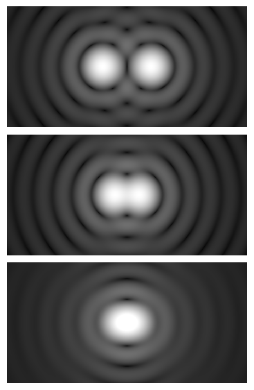
Two airy disks at various spacings: (top) twice the distance to the first minimum, (middle) exactly the distance to the first minimum (the Rayleigh criterion), and (bottom) half the distance.
This image uses a nonlinear color scale (specifically, the fourth root) in order to better show the minima and maxima.
These are close numerically and capture the same essential trend. In practice, the ability to resolve features also depends on signal-to-noise ratio, contrast mechanism, and detection threshold. Still, the proportionality to λ/NA is robust across modalities in the incoherent limit.
Axial resolution and sectioning
Axial resolution describes the ability to discriminate features along the optical axis (depth). For widefield systems, a common approximation for the diffraction-limited axial resolution is:
δz ≈ 2 n λ / NA2
Here, n is the refractive index of the medium and λ is the wavelength in vacuum. The 1/NA2 dependence shows why high-NA objectives provide improved optical sectioning compared with lower NA, even without confocal techniques. Confocal and structured illumination methods further tighten the effective axial response, but their theoretical expressions differ because they modify the illumination and detection pathways.
Wavelength selection
Shorter wavelengths improve resolution because both δ and d scale linearly with λ. However, practical constraints arise:
- Sample absorption and photodamage: Shorter wavelengths may be more strongly absorbed or scatter more, reducing signal or harming live specimens.
- Fluorophore spectra: In fluorescence, excitation and emission wavelengths are dictated by fluorophore properties. Emission wavelength influences the diffraction-limited spot size on the detector.
- Chromatic aberration: Objectives correct chromatic dispersion to specified degrees. Using wavelengths far from the design range can increase residual aberrations.
Because NA multiplies with 1/λ in the formulas, improving NA often yields larger returns than modest shifts in wavelength, especially when shorter wavelengths are not feasible for the sample.
Depth of Field, Depth of Focus, and NA Trade-offs
NA not only sets lateral resolution; it also strongly influences how much of the specimen is in acceptable focus at once. Two related concepts are important:
- Depth of field (DOF): The axial range in the specimen over which structures are acceptably sharp in the captured image.
- Depth of focus: The axial tolerance at the image plane (detector or eyepiece) over which the image remains acceptably sharp; this is on the detection side of the optics.
For diffraction-limited imaging, a useful proportionality is that DOF scales roughly like λ n / NA2 (with constants depending on criterion and coherence). This inverse-square dependence means that high NA delivers thin optical sections but requires more precise focusing and often more axial sampling for 3D imaging.
In camera systems, DOF also depends on the detector sampling and the definition of “acceptably sharp.” A common extended form is a sum of a diffraction term and a detector-sampling term; the latter becomes important when pixels are large or magnification is low. The key takeaways are:
- Increasing NA decreases DOF quickly.
- Larger magnification reduces the detector-limited DOF contribution. This is one reason that low-NA, low-magnification objectives can appear to have a forgiving focus range.
- For z-stacks and 3D reconstruction, axial step size should obey sampling criteria tied to the axial resolution. Using steps comparable to or smaller than δz helps avoid missing high-frequency axial information.
Depth of focus on the detection side increases with f-number; in microscopy the effective f-number relates inversely to NA. As NA rises, the permissible shift of the camera or eyepiece plane before noticeable blur becomes smaller, which is why high-NA imaging benefits from stable mechanics and precise parfocal alignment.
These relationships ripple into practical choices discussed in Practical Tuning and Aberrations and Working Distance.
Condenser Numerical Aperture and Matching the Objective
In transmitted-light modalities (e.g., brightfield, phase contrast, DIC), the condenser forms the illumination cone at the specimen. The condenser’s numerical aperture determines the range of angles at which the specimen is illuminated. To exploit the objective’s resolving power in these modalities, the illumination cone should generally fill a substantial portion of the objective’s entrance pupil.
A practical guideline is to adjust the condenser aperture so that its NA is similar to, but slightly lower than, the objective’s NA. This promotes high-contrast transfer of fine spatial frequencies while maintaining good image uniformity. If the condenser NA is set too low, the image becomes high-contrast but loses high-frequency detail; set too high, contrast can wash out and stray light or glare may increase.
In fluorescence microscopy, the objective also collects emitted light, and while the substage condenser is often not used for fluorescence excitation in the same way as transmitted modalities, the collection NA of the objective remains critical for sensitivity and resolution of emitted photons. The illumination path for fluorescence is typically epi-illumination through the objective; the emission is still bounded by the objective’s NA.
Key points for condenser/illumination NA management:
- Match condenser NA to objective NA (slightly lower) for brightfield to approach the objective’s spatial frequency passband.
- Use the condenser aperture diaphragm as a contrast and resolution control—closing it boosts depth of field and macro-contrast at the cost of fine detail; opening it improves resolution and micro-contrast while reducing depth of field.
- Ensure uniform, well-collimated illumination at the specimen plane so that changes in condenser NA behave as expected and do not introduce vignetting or hot spots.
These adjustments, in tandem with objective NA, shape the observable detail. For how this interacts with specific contrast techniques, see Choosing NA for Common Contrast Methods.
Choosing NA for Common Contrast Methods and Samples
Different contrast methods impose different demands on NA. Selecting the appropriate NA involves balancing resolution, light budget, sample thickness, and contrast mechanism.
Brightfield (transmitted light)
- Low NA (≤ 0.25): Good for overview scans, large depth of field, forgiving focus, and large field of view. Limited resolving power for subcellular detail.
- Moderate NA (0.40–0.65): Solid general-purpose range for histological sections and thin samples. Good balance of resolution and DOF.
- High NA (≥ 0.80): Resolves fine structures in thin sections. Requires precise focusing, careful illumination NA adjustment, and usually immersion media to go beyond ~0.95.
Phase contrast
Phase contrast translates phase variations into intensity differences via phase rings in the objective and matching annuli in the condenser. It works well at moderate NA (e.g., 0.3–0.95). Higher NA can be used, but alignment tolerances increase. The condenser annulus should be aligned to the objective’s phase ring, and the condenser aperture generally set appropriately for the phase annulus, not fully open.
Differential interference contrast (DIC)
DIC enhances gradients in optical path length and benefits from higher NA for fine detail. Objectives and prisms must be designed to match. DIC works across a wide NA range, but higher NA generally improves the sensitivity to small gradients and yields crisper detail. Precise polarization alignment is required, and sample anisotropy can influence contrast.
Fluorescence
Fluorescence emits isotropically; the fraction of emitted photons captured scales strongly with NA. High NA is therefore desirable for sensitivity and resolution. Oil-immersion objectives with NA ≥ 1.3 are common for detailed fluorescence imaging of thin specimens. For thick, aqueous samples, water-immersion objectives at high NA can outperform oil in practice by reducing spherical aberration with depth.
Reflected-light (epi) brightfield and polarized light
For polished materials or reflective samples, higher NA improves resolution and surface sensitivity, but working distance and geometry constraints often limit the achievable NA. Polarized light methods depend more on polarizer-analyzer alignment and sample anisotropy than on pushing to the absolute highest NA, though increased NA still improves lateral detail.
Ultimately, match NA to the sample’s thickness, refractive index environment, and the desired combination of resolution and depth of field. If your sample is thick and index-mismatched, a slightly lower NA water-immersion objective may outperform a higher-NA oil objective once aberrations are considered—see Aberrations and Working Distance.
Practical Tuning: Aperture Diaphragms, Pupil Fill, and Sampling
Translating NA theory into crisp images requires hands-on adjustments. Three practical levers are especially influential:
1) Aperture diaphragms and illumination NA
The condenser aperture diaphragm controls the illumination NA in transmitted-light imaging. Opening the diaphragm increases illumination angles, improving resolution and micro-contrast from fine detail at the expense of depth of field and overall macro-contrast. Closing it reduces those angles, increasing DOF and macro-contrast but attenuating high spatial frequencies. A good starting point is to set illumination NA to be a bit below the objective’s NA and then adjust to taste based on the specimen and the task.
2) Pupil fill and objective performance
Objectives are designed to be illuminated in a way that fills their pupil appropriately. If the illumination cone under-fills the pupil or is misaligned, the effective transfer of high-angle information degrades. In fluorescence with epi-illumination, ensuring the excitation beam uniformly fills the back aperture of the objective helps reach the intended effective NA for illumination. In transmitted light, the condenser NA setting affects how completely the objective pupil is illuminated from the specimen side.
3) Sampling on the camera
To realize the detail delivered by NA, the detector must sample sufficiently. Approximate Nyquist sampling for the lateral dimension can be expressed as a target pixel size at the specimen plane:
pixel size (specimen plane) ≤ 0.5 × (Rayleigh lateral resolution) ≈ 0.305 × λ / NA
Given a camera with pixel pitch pcam and total magnification M to the camera, the effective pixel size at the specimen plane is peff = pcam/M. Choose M so that peff satisfies the inequality for the wavelengths and NA used. Slight oversampling (smaller peff) is often beneficial for deconvolution and registration, at the cost of larger data and potentially lower SNR per pixel.
Example:
# Camera pixel = 6.5 µm, NA = 1.30, λ = 525 nm
λ = 525e-9
NA = 1.30
rayleigh = 0.61*λ/NA  # meters
nyquist_pix = 0.5 * rayleigh  # meters
nyquist_pix_um = nyquist_pix * 1e6
print("Target pixel at specimen ≈", nyquist_pix_um, "µm")
# To achieve this with 6.5 µm pixels, choose M so that 6.5/M ≤ nyquist_pix_um
This exercise reveals whether a given camera and magnification are under- or over-sampling relative to the NA-driven resolution.
Aberrations, Cover Glass, and Working Distance Constraints
Real objectives deviate from ideal diffraction-limited performance due to optical aberrations, sample-induced aberrations, and mechanical constraints. NA interplays with each of these.
Cover glass thickness and correction collars
Many high-NA objectives are designed for a specific cover glass thickness (often around 0.17 mm for standard coverslips labeled #1.5). Departures from the specified thickness or refractive index add spherical aberration, particularly at high NA. Some objectives include a correction collar that allows the user to compensate for deviations in cover glass thickness and, to some extent, the sample’s refractive index mismatch. Correct use of the collar can markedly improve contrast and sharpness when imaging through non-ideal covers or mounting media.

Leica microscope objective PL FLUOTAR 100x, oil immersion, aperture 1,30, cover glass 0,17 mm, PH3; DIC prism D
Key practices:
- Use cover glasses that match the objective’s specification.
- When available, adjust the correction collar for your sample and verify by focusing through fine structures while observing contrast and sharpness.
- Recognize that the effective benefit of NA can be compromised by uncorrected spherical aberration; sometimes a slightly lower nominal NA with better correction performs better in practice.
Working distance and mechanical clearance
Working distance is the space between the objective front lens and the specimen when in focus. As NA increases, working distance generally decreases. This can limit access to thick samples, microfluidic devices, or samples with covers or holders. Be mindful that some high-NA objectives bring the front lens very close to the coverslip; safe handling and clean immersion application are essential.
Sample-induced aberrations
Index heterogeneity across depth (e.g., a thick, watery specimen under oil immersion) introduces wavefront distortions that degrade resolution, more so at higher NA. Matching immersion media to the sample environment (see Immersion Media) and using objectives designed for specific media can mitigate these effects. In advanced setups, adaptive optics can compensate for aberrations by modifying the wavefront, but that is beyond the scope of standard light microscopy.
Chromatic and field aberrations
Objectives are manufactured with different correction levels for chromatic and geometric aberrations. Terms you may encounter include achromat, fluorite/semi-apochromat, and apochromat, indicating progressively tighter correction across wavelengths and field. While higher correction often correlates with higher NA, they are distinct aspects; you can find moderate-NA objectives with excellent color correction and high-NA objectives with specialized corrections optimized for specific tasks. Choose based on both NA and the corrections your application requires.
Frequently Asked Questions
How does NA relate to the brightness of a fluorescence image?
Fluorescence emission is generally isotropic, meaning photons are emitted in many directions. The objective collects a portion of those photons within its acceptance cone; the size of that cone is set by NA. For a given specimen and fluorophore, increasing NA increases the solid angle over which emission is collected, leading to more detected signal. In addition, higher NA improves the concentration of light into smaller diffraction-limited spots, which can increase peak intensity at the detector. Overall, higher NA improves both sensitivity and resolution in fluorescence imaging, at the cost of shallower depth of field and, often, shorter working distance.
Can I improve resolution just by using a higher-power eyepiece or adding a camera relay lens?
No. Eyepiece magnification and camera relays change the size of the image, not the optical information content captured by the objective. If the objective’s NA limits the highest spatial frequencies that reach the image plane, increasing magnification will not reveal new detail; it will only enlarge the existing diffraction-limited image. To gain true resolution, you need higher NA (and possibly shorter wavelengths) along with proper alignment and sampling. However, adjusting magnification can help match the image to the detector’s pixel size to meet Nyquist sampling without incurring empty magnification.
Final Thoughts on Choosing the Right Numerical Aperture
Numerical aperture is the keystone parameter that ties together resolution, light collection, depth of field, and practical imaging constraints in light microscopy. The core physics is succinct: NA = n × sin(θ), and higher NA improves lateral and axial resolution approximately as 1/NA and 1/NA2, respectively, while increasing light throughput. Yet, maximizing NA is not always the optimal choice. Immersion medium compatibility, sample thickness, refractive index mismatch, working distance, and the need for manageable depth of field all influence the ideal NA for a given task.
To select wisely:
- Define the smallest features you need to resolve and estimate the necessary NA using the resolution criteria.
- Choose the immersion medium to match the specimen’s environment and minimize spherical aberration (see Immersion Media).
- Set condenser aperture to a value slightly below the objective’s NA to balance contrast and resolution in transmitted-light imaging (Condenser NA).
- Verify camera sampling against the NA-limited resolution to avoid under- or over-sampling (Practical Tuning).
- Confirm cover glass compatibility, consider correction collars if available, and be mindful of working distance constraints (Aberrations and Working Distance).
When you bring these elements into alignment, the improvement in clarity is striking—even without changing magnification. Understanding and leveraging NA empowers you to diagnose image quality issues, make purposeful trade-offs, and design experiments that extract the most from your optics.
If you found this guide useful, explore our other microscopy fundamentals and consider subscribing to our newsletter for future deep dives into optics, contrast methods, and practical workflows that make microscopy more effective and enjoyable.

A: Microscope Ernst Leitz oil-immersion microscope; instrument rests on wishbone-shaped base with a single beam extending from the center before splitting into two sections: an arm supporting the telescope and microscopic lenses and a round stand for slides; below the stage is a double-sided mirror that rotates 360 degrees; the stage has a round hole in the middle allowing light to come up through the mirror and two metal stage clips that pivot to hold slides in place; an additional lens below the stage helps focus the light; the telescope has a monocular eye piece with 8x magnification and a rotating nose with three objective lenses (3, 6L, and 1/12); the telescope arm can be raised and lowered using knobs on the side. B: Wooden Carrying Case Wooden carrying case, painted lighter brown on outside; two metal latches close box; metal handle on top for carrying; shelf at top holds attachments and accessories (C-G); attachments on bottom and door of box hold the microscope in place; card on door provides serial number and magnification information. C: Vial of Oil Small brown glass vial with black lid, contains oil used for oil-immersion technique; approximately half full of liquid. D: Wooden Rack Wooden rack that fits on the top shelf of the instrument box (B), contains 13 round holes of various sizes for the holding of instrument accessories. E: Eyepiece A black eyepiece with 6x magnification. F: Storage Containers Three empty black plastic canisters with matching screwtops, canisters appear to have once held objective lenses currently attached to microscope, numbers on top of canisters match those on objectives. G: Booklet Small pamphlet with information about the instrument, written in German, with two pages of text and picture of instrument, dated April 1943.


