
Table of Contents
- What Is Numerical Aperture (NA) in Light Microscopy?
- Diffraction-Limited Resolution: Abbe, Rayleigh, and Practical Limits
- Why Köhler Illumination and Condenser NA Matter for Image Quality
- Contrast Mechanisms: Brightfield, Phase, DIC, and Darkfield
- Digital Sampling, Pixel Size, and Nyquist Criteria for Microscopy Cameras
- Depth of Field, Axial Resolution, and Refractive Index Mismatch
- Immersion Media, Refractive Index, and Working Distance Trade-offs
- Magnification Versus Resolution: Avoiding Empty Magnification
- Practical Checklist to Optimize Resolution and Contrast
- Frequently Asked Questions
- Final Thoughts on Optimizing NA, Resolution, and Contrast
What Is Numerical Aperture (NA) in Light Microscopy?
Numerical aperture (NA) is one of the most important specifications of any microscope objective or condenser. It directly governs the resolving power, light-gathering ability, and contrast potential of an optical system. In simple terms, NA describes how widely an objective can accept light rays emerging from the specimen and how efficiently a condenser can deliver illumination to the specimen.
Formally, numerical aperture is defined as:
NA = n · sin(θ)
where n is the refractive index of the medium between the specimen and the objective lens front element (e.g., air, water, or oil) and θ is the half-angle of the maximum cone of light that the lens can accept. A larger NA captures higher-angle rays, which carry higher spatial frequencies, yielding finer detail. This is why a high-NA 60× or 100× objective typically resolves more than a lower-NA 40× objective, even if the lower-NA lens has similar magnification.

Artist: PaulT (Gunther Tschuch)
Key implications of NA in practice:
- Resolution scales inversely with NA. Higher NA reduces the minimum resolvable distance between features. See Diffraction-Limited Resolution for details.
- Brightness increases with NA. For incoherent illumination, the collected intensity generally increases with the solid angle of acceptance. In fluorescence microscopy, higher NA also collects more emitted photons from point sources, improving the signal-to-noise ratio.
- Depth of field decreases as NA increases. Shallow depth of field is a consequence of high NA focusing properties; see Depth of Field and Axial Resolution.
- Working distance tends to decrease as NA increases. High-NA objectives often have short working distances; we discuss this trade-off under Immersion Media and Working Distance.
Because NA depends on the medium refractive index, immersion objectives (e.g., oil or water) can reach higher NA than comparable air objectives. However, achieving the theoretical performance of a high-NA system requires optimal illumination (see Köhler Illumination), careful focusing, and correct sampling at the camera or eyepiece plane (see Digital Sampling).
Diffraction-Limited Resolution: Abbe, Rayleigh, and Practical Limits
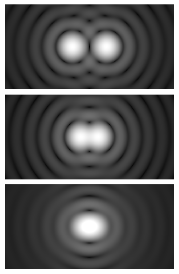
Even a perfect, aberration-free lens cannot form infinitely sharp images due to the wave nature of light. Diffraction spreads a point source of light into a pattern called the point spread function (PSF), whose central bright disk is the Airy disk. The finite size of the Airy disk sets a fundamental limit on resolution; two point objects must be sufficiently separated for their Airy disks to be distinguished.
There are several closely related criteria for lateral (x–y) resolution in conventional brightfield and widefield fluorescence microscopy. A frequently used one is the Rayleigh criterion:
d_Rayleigh ≈ 0.61 · λ / NA
Artist: Spencer Bliven
Here, λ is the imaging wavelength and NA is the objective’s numerical aperture. The constant (0.61) depends on the chosen criterion and the degree of coherence of the illumination. Under different assumptions, related forms appear (e.g., ~0.5–0.61 × λ/NA). For practical microscopy, quoting the Rayleigh value is common and provides a realistic estimate.
For axial (z) resolution in widefield systems, a widely used estimate is:
Δz ≈ 2 · n · λ / NA²
where n is the refractive index of the medium. Axial resolution improves with higher NA but is typically poorer than lateral resolution by a factor of several. Confocal and structured illumination systems can improve axial discrimination, but the specific improvement depends on the modality and settings and is beyond the scope of this fundamentals overview.
Key point: Decreasing the wavelength (e.g., imaging in the blue–green range) and increasing NA both improve the smallest resolvable detail. The trade-offs of higher NA (reduced depth of field, shorter working distance) are addressed in Immersion Media and Working Distance.
Lateral resolution example
Suppose you image at λ = 550 nm (green light). For NA = 0.65 (common for a 40× air objective), Rayleigh resolution is approximately:
d ≈ 0.61 × 0.55 µm / 0.65 ≈ 0.516 µm
For NA = 1.40 (a typical high-NA oil objective):
d ≈ 0.61 × 0.55 µm / 1.40 ≈ 0.240 µm
This simple comparison illustrates why high-NA optics can reveal substantially finer detail, assuming correct illumination, focus, and sampling.
Resolution, contrast, and detectability
Even if two points are separated by the Rayleigh distance, they might not be visually distinguishable without adequate contrast. Resolution sets the theoretical boundary of detail, while contrast determines whether that detail is detectable above background noise. Illumination strategy and contrast methods (see Contrast Mechanisms) strongly influence whether fine details become visible in practice.

Artist: Anaqreon
Why Köhler Illumination and Condenser NA Matter for Image Quality
Köhler illumination is a method of setting up transmitted light microscopy so that the specimen is illuminated uniformly and the light source structure (e.g., filament or LED die) is not imaged into the field. It establishes two sets of conjugate planes: the field diaphragm is imaged at the specimen plane, and the aperture diaphragm is imaged at the objective’s back focal plane.

Artist: ZEISS Microscopy
The role of the condenser
The condenser lens focuses illumination onto the specimen and sets the angular distribution of light arriving at the sample. Its numerical aperture should be matched to the objective’s NA for optimal resolution and contrast in brightfield. If the condenser NA is significantly lower than the objective NA, the full resolving potential of the objective is not realized. Conversely, opening the condenser aperture too wide can reduce contrast due to increased glare and stray light.
Practical guidance for brightfield imaging:
- Set the field diaphragm to just circumscribe the field of view: this reduces stray light and improves contrast without cutting off the image.
- Adjust the aperture diaphragm (condenser iris) to approximately 60–90% of the objective NA, depending on the specimen and desired contrast. Closing the iris improves contrast at the expense of resolution and brightness; opening it increases resolution and brightness but can lower contrast.
- Focus the condenser so that the field diaphragm is sharply imaged in the specimen plane when checked during Köhler setup.
These settings are interactive. If your specimen is low-contrast and you struggle to detect fine detail, it can be productive to slightly reduce the effective condenser NA to trade some resolution for more contrast. If you are trying to resolve the very finest structures, open the aperture to better match the objective NA and ensure you meet the sampling requirements discussed in Digital Sampling.
Illumination uniformity and color
Uniform, stable illumination promotes reproducible contrast and accurate color rendering. In white-light imaging, chromatic properties of the objective and illumination spectrum can affect color balance and apparent sharpness. For fluorescence microscopy, illumination wavelength bands are set by excitation filters and the emission is selected by emission filters; resolution is determined by the emission wavelength and objective NA. Whenever you switch fluorophores, remember that resolution depends on λ; longer-wavelength emission typically yields slightly lower resolution, all else equal.
Contrast Mechanisms: Brightfield, Phase, DIC, and Darkfield
Specimens often transmit or emit only small fractions of light differences relative to the background, especially in transparent samples. Multiple contrast methods convert subtle optical path differences, refractive index variations, or scattering into intensity variations that the eye or camera can detect. Choosing the right contrast method can be as important as selecting the right NA.
Brightfield
In brightfield, contrast arises from absorption, scattering, and phase effects that convert to amplitude differences. It is the most common and simplest mode. Proper Köhler illumination and careful matching of condenser and objective NA are essential for maximizing brightfield contrast without sacrificing necessary resolution.
Phase contrast
Phase contrast introduces a phase ring in the objective pupil and an annulus in the condenser to convert phase shifts (caused by refractive index and thickness variations) into intensity differences. This is especially useful for thin, transparent specimens. Because phase contrast modifies the pupil function, it can slightly affect the effective NA and transfer of certain spatial frequencies. Fine, halo-like artifacts around edges are normal. When resolving the smallest details is critical, compare results with brightfield or DIC to assess which modality preserves detail best for your specimen.
Differential interference contrast (DIC)
DIC converts phase gradients into intensity differences by shearing two orthogonally polarized, laterally displaced beams through the specimen and recombining them in the analyzer. It provides high-contrast, quasi-shadowed images that emphasize edges and fine relief. DIC generally preserves higher spatial frequencies well and can be an excellent companion to high-NA objectives for assessing fine structure. However, interpretations should consider that DIC encodes gradients, not absolute thickness.
Darkfield
Darkfield excludes the directly transmitted beam from the objective by using a hollow-cone illumination (e.g., with a specialized condenser). Only light that is scattered by the specimen enters the objective, forming bright features on a dark background. To achieve effective darkfield, the condenser NA must typically exceed the objective NA so that direct illumination is not collected. Darkfield enhances visibility of sub-resolution scatterers by converting them to bright spots, but it does not increase the true diffraction-limited resolution.
Polarization-based methods
Polarized light microscopy leverages birefringence to generate contrast, informative for anisotropic materials. While not as broadly applied as brightfield, phase, or DIC, it can reveal structural information not otherwise visible, particularly in crystalline or fibrous materials.
Selecting the right contrast method improves detectability—the likelihood that features near the resolution limit are visible with sufficient signal-to-noise. For example, a high-NA objective under DIC might reveal edges that are hard to detect in brightfield even if the nominal resolution limit is identical. Integrate contrast choices with NA, illumination, and sampling to make the most of your system.
Digital Sampling, Pixel Size, and Nyquist Criteria for Microscopy Cameras
Digital imaging introduces an additional requirement beyond optical resolution: sampling. Even if your optics resolve fine detail, insufficient sampling by the camera pixels will lose spatial information or create artifacts (aliasing). The Nyquist sampling criterion states that the sampling frequency must be at least twice the highest spatial frequency present in the image to reconstruct it without aliasing.
Object-space pixel size and total magnification
To check sampling, convert the camera pixel size to the specimen plane by dividing by the total magnification between specimen and sensor. For a camera with pixel size p (in µm) and total magnification M_total (objective × intermediate optics such as tube lens factors or camera adapters), the specimen-plane pixel size is:
p_object = p / M_total
To satisfy Nyquist for a system with Rayleigh lateral resolution d_Rayleigh, a common rule of thumb is:
p_object ≤ (0.33 to 0.5) × d_Rayleigh
The more conservative value (≈0.33 × d) provides additional sampling headroom. Using the Rayleigh expression d_Rayleigh ≈ 0.61 λ / NA, you can write:
p_object ≤ (0.33 to 0.5) × 0.61 × λ / NA
From this, you can solve for a suitable total magnification for a given camera pixel size and objective NA. Because the optimal value depends on the wavelength and the desired sampling margin, it is typical to choose a total magnification that yields 2–3 pixels across the smallest resolvable feature.
Worked example
Assume a camera with 6.5 µm pixels, imaging at λ = 550 nm with an objective of NA = 1.40. Rayleigh resolution is ~0.240 µm. Setting p_object to ~0.12 µm (≈d/2) would satisfy Nyquist. Then the total magnification should be:
M_total = p / p_object ≈ 6.5 µm / 0.12 µm ≈ 54×
In practice, a 60× objective without additional relay optics often provides suitable sampling with 6.5 µm pixels at this NA and wavelength. If your camera has smaller pixels (e.g., ~3.45 µm), you may achieve adequate sampling at lower total magnification; conversely, larger pixels may call for additional magnification.
Aliasing and practical signs of undersampling
- Moire or repeating patterns near high-contrast edges can signal undersampling.
- Pixelated or blocky appearance at compromise magnifications can mean you are not sampling fine details adequately.
- Measured line profiles across sharp edges appear smeared or asymmetric when sampling is insufficient.
To correct undersampling, increase total magnification at the camera, use an objective with higher magnification (assuming similar NA), or choose a camera with smaller pixels. Keep in mind that magnification alone does not improve optical resolution—see Magnification Versus Resolution—but appropriate magnification is essential to capture the resolution your optics can deliver.
Depth of Field, Axial Resolution, and Refractive Index Mismatch
Depth of field (DOF) refers to the axial range over which the specimen appears acceptably sharp in an image. As NA increases, depth of field decreases. This is a geometric-optical consequence of high-angle rays contributing to the image. For widefield imaging, a commonly used relationship for DOF includes a term proportional to λ · n / NA², indicating that higher NA and shorter wavelengths reduce the axial extent of acceptable focus. While exact DOF expressions depend on imaging criteria and system details, the general inverse-squared dependence on NA is robust.
Axial resolution vs. DOF
Axial resolution (Δz ≈ 2 n λ / NA²) estimates how closely two features can be resolved along the optical axis; DOF describes how thick a single feature can be while remaining visually sharp. Both scale inversely with NA², but they are not identical. In practice, shallow DOF at high NA can make focusing more challenging and can emphasize refractive index mismatches that degrade image quality.
Refractive index mismatch and spherical aberration
Spherical aberration arises when light rays at different radial distances from the optical axis focus at different depths, often caused by refractive index mismatches between the specimen environment and the imaging medium. The effect becomes more pronounced with depth and higher NA, broadening the PSF and reducing contrast and resolution—especially along the z-axis.
To mitigate index-mismatch effects:
- Match the immersion medium to the objective’s design when using immersion objectives (see Immersion Media).
- Use wavelengths where the system is well-corrected; chromatic aberration can interact with index mismatches.
- Minimize imaging depth in media with strong index inhomogeneity when high-NA resolution is critical.
These strategies help preserve the high spatial frequencies that high-NA objectives are designed to transmit.
Immersion Media, Refractive Index, and Working Distance Trade-offs
Because NA = n · sin(θ), increasing the refractive index n of the imaging medium directly allows higher NA for the same acceptance angle. This is the basis for immersion objectives, which are designed to operate with a specific medium between the front lens and the specimen interface.
Common immersion media and NA potential
- Air (n ≈ 1.00): Typical objectives reach NA up to about 0.95 in air, beyond which the required angles approach grazing incidence and performance becomes impractical.
- Water (n ≈ 1.33): Enables higher NA than air under similar angles; water-immersion objectives often provide improved performance for aqueous specimens and can reduce mismatch-induced aberrations in such environments.
- Oil (n ≈ 1.515, typical value): Permits very high NA (e.g., ~1.3–1.49 for many designs), increasing resolution and photon collection efficiency. The exact permissible NA depends on objective design.
- Glycerol (n ≈ 1.47, typical value): Offers a refractive index between water and oil; useful when matching intermediate indices in certain specimens or media.

Artist: Thebiologyprimer
These values are typical and can vary with temperature and formulation. Always use the immersion medium specified by the objective manufacturer for the design NA.
Working distance and mechanical constraints
High-NA objectives typically have shorter working distances than lower-NA objectives of similar magnification. This is a geometric consequence: collecting high-angle rays requires a larger front lens element closer to the specimen. Short working distances can complicate handling and focusing, especially with thick or uneven samples.
Considerations when choosing high-NA optics:
- Specimen clearance: Ensure adequate clearance to avoid contacting the specimen with the objective.
- Stability and vibration: Shallow DOF requires stable mounting and careful focusing to avoid blur.
- Illumination matching: Pair high-NA objectives with appropriate condenser NA and Köhler setup (see illumination).
These practicalities are worth planning for when you aim to exploit the full resolving power of high-NA objectives.
Magnification Versus Resolution: Avoiding Empty Magnification
Magnification enlarges the image; Resolution determines how much detail exists to be enlarged. Empty magnification occurs when you increase magnification without gaining new detail because the optical system has already reached its resolution limit or because the camera sampling is inadequate.
To avoid empty magnification:
- Match magnification to NA and wavelength so that camera pixels sample the optical resolution adequately (Nyquist sampling).
- Prioritize NA over magnification when choosing objectives for resolving power. A high-NA 40× lens may resolve more than a lower-NA 60× lens.
- Use intermediate magnification judiciously (e.g., 1.6× couplers) to meet sampling needs without exceeding optical limits.
When observing by eye through eyepieces, similar principles apply. Eyepiece magnification should make the smallest resolvable detail just visible to the human eye’s acuity without causing strain. In digital imaging, however, the camera’s pixel size and the display scale primarily determine whether magnified details are genuinely informative or merely larger.
Practical Checklist to Optimize Resolution and Contrast
Maximizing image quality is an exercise in balancing NA, illumination, contrast method, sampling, and specimen requirements. Use this practical checklist to reach a good starting point and iterate from there for your specific sample.
1) Start with alignment and cleanliness
- Ensure the optical path is clean: objective front lens, condenser top lens, and any relay optics.
- Verify mechanical stability and parfocality across objectives.
- Use proper Köhler illumination: set and focus the field diaphragm, then set the condenser aperture.
2) Choose the right objective and NA
- Select the highest NA compatible with your specimen’s thickness and working distance constraints (trade-offs).
- Balance resolution and depth of field for your task (depth and axial considerations).
3) Match condenser NA to objective NA (for transmitted modes)
- Open the condenser aperture to approach the objective NA when resolving fine detail.
- Close slightly to enhance contrast for low-contrast specimens at the cost of some resolution.
4) Select the appropriate contrast method
- Brightfield for general purpose and absorbing or scattering features.
- Phase contrast for thin, transparent specimens.
- DIC for edge-sensitive, high-contrast imaging with minimal halo.
- Darkfield for highlighting sub-resolution scatterers without increasing true resolution.
5) Verify sampling with your camera
- Compute
p_object = p / M_totaland compare to(0.33–0.5) × d_Rayleigh(Nyquist). - Adjust total magnification or select a camera with suitable pixel size to avoid undersampling.
6) Optimize wavelength and filters
- For fluorescence, remember resolution depends on emission wavelength; shorter emission bands generally yield finer resolution (resolution and λ).
- Use stable, flat-field illumination and appropriate filters to maintain consistent contrast.
7) Minimize aberrations and index mismatch
- Use the specified immersion medium for the objective (immersion media).
- Limit imaging depth when high-NA detail is essential to reduce spherical aberration effects (axial considerations).
8) Validate with a resolution target or known structures
- Check that line pairs or bead images align with expected resolution performance.
- Measure PSF or edge responses if quantitative imaging is required.
Frequently Asked Questions
Is higher NA always better for my images?
Higher NA generally improves both resolution and light collection, which is often beneficial. However, it reduces depth of field and working distance, increases sensitivity to refractive index mismatch, and can be more demanding of illumination quality and mechanical stability. If your specimen is thick or uneven, or if you need more axial tolerance, a slightly lower NA can sometimes yield more practical, usable images. Consider the trade-offs discussed in Depth of Field and Axial Resolution and Immersion Media and Working Distance, and ensure sampling is adequate (Digital Sampling).
How does wavelength choice affect resolution and contrast?
Resolution scales with wavelength as d ≈ 0.61 λ / NA, so shorter wavelengths improve lateral resolution. In fluorescence imaging, the emission wavelength determines resolution, while in transmitted light, the illumination spectrum and objective corrections influence effective sharpness and color fidelity. Shorter wavelengths can also increase scattering and absorption for some specimens, affecting contrast. Choose wavelength bands that balance resolution, specimen compatibility, and detector sensitivity, and remember to adapt sampling if you change λ significantly (Nyquist criteria).
Final Thoughts on Optimizing NA, Resolution, and Contrast
Numerical aperture, diffraction-limited resolution, illumination strategy, and contrast modality work together to define what you can see and measure with a light microscope. The essential relationships are straightforward: higher NA and shorter wavelengths improve resolution; careful Köhler illumination and condenser NA matching conserve contrast; and correct digital sampling ensures that cameras capture the optical detail your system delivers. The art lies in balancing these factors against specimen properties, depth of field needs, and practical constraints like working distance and stability.
By applying the checklists and concepts in this guide, you can diagnose common image-quality issues, avoid empty magnification, and consistently approach the true performance limits of your objectives. If you enjoyed this fundamentals deep dive and want more technically rigorous yet approachable microscopy content, consider subscribing to our newsletter to receive future articles on optics, illumination, and imaging best practices.

Artist: Ernst Leitz (Firm)


