Table of Contents
- What Do Numerical Aperture, Resolution, and Magnification Mean?
- How Numerical Aperture Sets Diffraction-Limited Resolution
- Magnification vs. Resolution: Avoiding Empty Magnification
- Wavelength, Illumination, and Contrast: Their Impact on Detail
- Practical Choices: Objective NA, Immersion Media, and Condenser NA
- Depth of Field, Field of View, and Contrast Transfer
- Sampling, Cameras, and Displays: Matching Pixels to Optics
- Common Misconceptions About NA, Resolution, and Magnification
- Frequently Asked Questions
- Final Thoughts on Choosing the Right Numerical Aperture and Magnification
What Do Numerical Aperture, Resolution, and Magnification Mean?
When exploring optical microscopy, three tightly linked concepts govern how much detail you can actually see: numerical aperture (NA), resolution, and magnification. Understanding how these terms relate—physically and mathematically—helps you set up a microscope to extract real information from your specimen rather than just making a blurry image look bigger. This section defines the terms in plain language and sets the stage for deeper discussions in how NA sets resolution, how wavelength and illumination matter, and how to match a camera to the optics.
Numerical aperture (NA)
Numerical aperture is a dimensionless number that characterizes the angular range of light an optical system (e.g., an objective or a condenser) can accept or deliver, scaled by the refractive index of the imaging medium. For an objective lens, it is defined as NA = n sin(θ), where:
- n is the refractive index of the medium between the specimen and the objective’s front lens (e.g., air, water, immersion oil).
- θ is half the angular aperture of the objective (the half-angle of the cone of light the objective collects from the specimen).
Higher NA means the objective gathers higher-angle diffracted light, which carries finer spatial information about the specimen. In practical terms, higher NA is the principal path to finer spatial resolution in optical microscopy.
Resolution
Resolution describes the smallest feature spacing that can be distinguished as separate in the image. In classical, diffraction-limited optics, resolution is not the same as magnification; it is set primarily by the wavelength of light and the system’s numerical aperture. Several formal criteria are used in microscopy:
- Rayleigh criterion (point-separation): two point sources are considered just resolvable when the central maximum of one Airy pattern coincides with the first minimum of the other, giving a lateral resolution scale of approximately
r ≈ 0.61 λ / NA. - Abbe limit (periodic structures): the finest resolvable period of a sinusoidal grating under incoherent imaging is often expressed as
d ≈ λ / (2 NA).
These two expressions are closely related and of the same order; you will often see both in microscopy literature. Throughout this article, we will use them contextually and explain when each is most relevant in the resolution section.
Attribution: Public domain (CC0).
Magnification
Magnification is how large the image appears, either through eyepieces or on a sensor/display. There are multiple magnifications in a microscope system (objective, tube lens, eyepiece, and camera projection), and only the total system magnification seen by your eye or by a camera matters for the size of the final image. However, magnification does not inherently add detail; it only scales the image. Detail is governed by resolution and sampling. Excessive magnification relative to resolution is called empty magnification, a topic explored in the magnification vs. resolution section.
Key takeaway: Resolution is set by wavelength and NA; magnification only enlarges what’s already there. Use NA and proper illumination to capture detail, and choose magnification to present that detail usefully.
How Numerical Aperture Sets Diffraction-Limited Resolution
At the heart of optical microscopy lies diffraction: light scattered by fine features in the specimen interferes to form an image with a spatial frequency limit. Numerical aperture determines which diffracted angles—and thus which spatial frequencies—are admitted by the objective. This is why NA appears in elementary resolution formulas.
Rayleigh and Abbe: two sides of the same coin
Two widely cited metrics describe lateral resolution in brightfield and fluorescence microscopy under incoherent or partially coherent imaging:
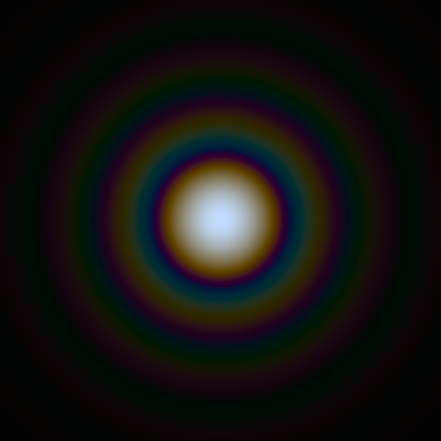
- Rayleigh criterion (point-separation): The distance between two point emitters (or small beads) that are just resolved is approximately
r ≈ 0.61 λ / NA. Here,λis the relevant emission or detection wavelength. - Abbe limit (periodic structures): The finest period
dof a sinusoidal grating that can be imaged isd ≈ λ / (2 NA).
These formulas are not contradictory; they describe slightly different resolution tasks (isolated points versus periodic detail) but share the same dependency: finer detail requires shorter wavelength and larger NA. The constant factors (0.61 versus 0.5) reflect different criteria for what counts as “resolved.” In fluorescence imaging, for example, you usually use the emission wavelength in these expressions, since the emitted light forms the image. In transmitted brightfield, the illumination wavelength and imaging geometry govern the transfer of spatial frequencies; we revisit this nuance in the section on wavelength and illumination.

This image uses a nonlinear color scale (specifically, the fourth root) in order to better show the minima and maxima.
Attribution: Public domain.
Axial (z) resolution and high-NA imaging
Lateral resolution is not the whole story. Optical sectioning methods (e.g., confocal or structured illumination) and high-NA objectives also affect axial resolution—the ability to distinguish features at different depths. While detailed axial formulas depend on imaging modality and coherence, a general qualitative trend holds: axial resolution improves (the section thickness becomes thinner) as NA increases and as wavelength decreases. High-NA, immersion objectives typically deliver significantly better axial sectioning than low-NA, air objectives in otherwise similar conditions.
Condenser NA and partial coherence
In transmitted-light microscopy, not only the objective’s NA but also the condenser’s NA and the coherence of illumination influence the spatial frequencies that are transferred with good contrast. Partial coherence is the typical regime in Köhler illumination. Adjusting the condenser aperture changes the degree of illumination angular diversity, which in turn affects contrast and the effective imaging transfer. As a rule of thumb, opening the condenser aperture increases resolution and brightness but reduces specimen contrast; stopping it down increases contrast but sacrifices high-frequency transfer. Practical guidance is covered in Wavelength, Illumination, and Contrast.
Resolution is not the same as sharpness
Images can look “sharper” when edges have high contrast, even if the system’s diffraction-limited resolution has not changed. Conversely, genuinely higher resolution may look underwhelming if contrast is low or if the camera undersamples the image. To truly achieve the resolution implied by a high-NA objective, you need appropriate illumination, a well-aligned condenser (when applicable), proper coverslip thickness, and adequate sampling. We connect these pieces in Sampling, Cameras, and Displays.
Magnification vs. Resolution: Avoiding Empty Magnification
Magnification is indispensable for inspection and measurement, but it can easily be misapplied. Empty magnification happens when you enlarge an image beyond the system’s resolvable detail. The picture gets bigger but not better. Learning how to choose magnification relative to resolution and sampling helps you avoid this trap.
Visual observation and useful magnification
Human visual acuity and display constraints mean that, for direct viewing through eyepieces, not all magnifications are equally helpful. A common guideline is to select total magnification so that the smallest resolvable features (set by NA and wavelength) are presented at a size your eye can discriminate comfortably. In practice, this equates to scaling the diffraction-limited resolution to a few arcminutes on the retina, which many practitioners operationalize as a magnification range that makes the finest details appear neither minuscule nor needlessly enlarged. While the exact value depends on viewing conditions (observer, eyepieces, and lighting), the principle remains: choose magnification to match the available resolution rather than to exceed it arbitrarily.
Digital imaging and sampling-limited magnification
For cameras, the relevant question is sampling, not human visual acuity. The sensor’s pixel pitch, combined with the system’s total magnification onto the sensor, sets the sampling interval at the specimen plane. Define:
- Pixel pitch (sensor):
p(e.g., in micrometers). - Total magnification onto the sensor:
M(objective magnification times any additional relay/tube lens factor affecting the camera). - Effective pixel size at the specimen plane:
p_eff = p / M.
To capture diffraction-limited detail without aliasing, you generally want multiple pixels across the smallest resolvable feature. A widely used sampling criterion is to set p_eff at about half (or somewhat less than half) of the expected resolution scale so that the highest transmitted spatial frequencies are sampled adequately. In many practical settings, aiming for roughly 2–3 pixels across the full width of the smallest features provides a reasonable balance between resolution capture and noise performance. See worked examples in Sampling, Cameras, and Displays.
Why empty magnification is misleading
Once your sampling is sufficient to capture the optical resolution, further magnification (either optically or digitally) enlarges the same information. Oversampling the same diffraction-limited spot over many pixels can improve certain measurements (e.g., centroiding of bright spots), but it does not add new spatial frequencies to the image in standard widefield imaging. In other words, more magnification does not change the cutoff in the system’s optical transfer function set by wavelength and NA.
Balanced decision-making
Choosing magnification should be a balancing act among:
- Optical resolution available from the objective’s NA and wavelength (see resolution formulas).
- Illumination and contrast that actually transfer high frequencies (illumination section).
- Sampling sufficient to capture the finest details without aliasing (sampling section).
- Signal-to-noise ratio (SNR) and exposure limits (especially in fluorescence, where photobleaching and phototoxicity impose practical limits).
By aligning these elements, you sidestep empty magnification and instead present genuinely resolved structure at sizes appropriate for viewing and quantification.
Wavelength, Illumination, and Contrast: Their Impact on Detail
While the objective’s NA is the main lever for resolution, illumination conditions and wavelength fundamentally influence which spatial frequencies reach the image sensor or your eye. This section explores how shorter wavelengths, illumination geometry, and condenser settings affect achievable detail and contrast.
Shorter wavelengths improve diffraction-limited resolution
Resolution scales with wavelength: shorter wavelengths produce smaller diffraction blur and thus finer resolvable detail, assuming the optics and detector can handle them. For example, moving from red to green to blue light tightens the point spread function laterally, all else equal. In fluorescence microscopy, the relevant λ in the Rayleigh expression is the emission wavelength captured by the detection optics. In transmitted brightfield, the illumination spectrum and filters shape the effective wavelength contributing to image contrast and resolution.
Coherence and condenser NA in transmitted light
In brightfield microscopy under Köhler illumination, the condenser focuses an image of the illumination aperture into the objective pupil, controlling the angular diversity of illumination. Several practical consequences follow:
- Opening the condenser aperture (higher illumination NA) increases the range of incident angles, facilitating transfer of higher spatial frequencies and increasing image brightness. However, it may lower contrast for weakly absorbing or low-contrast specimens.
- Stopping down the condenser (lower illumination NA) increases contrast and depth of field but reduces the highest spatial frequencies transmitted with appreciable contrast.
- Matching illumination NA to objective NA helps utilize the objective’s full resolution potential. In many routine setups, practitioners set the condenser aperture to a fraction of the objective’s NA to balance contrast and resolution; the exact setting depends on the specimen and imaging goal.

Partial coherence complicates simple resolution formulas, but the central idea is that both collection (objective NA) and illumination (condenser NA) shape the image’s spatial frequency content. Carefully aligning Köhler illumination and tuning the condenser aperture are essential to approach the resolution implied by the objective’s NA. See practical guidance in Practical Choices: Objective NA and Condenser NA.
Phase and contrast-enhancing modes
For weakly absorbing specimens, contrast-enhancing techniques such as phase contrast, differential interference contrast (DIC), and darkfield alter the illumination and detection paths. While these methods can dramatically improve visibility of fine structure, the apparent “sharpness” may reflect changes in contrast rather than a change to the diffraction-limited cutoff. For example, darkfield highlights high-angle scatter, potentially emphasizing edges, but the ultimate cutoff frequency still depends on the system’s NA and the method’s geometry.
Fluorescence detection considerations
In epifluorescence, the excitation light and emission light are spectrally separated. Resolution (as seen by the camera) depends primarily on the emission wavelength and objective NA. Filters and dichroic mirrors should be chosen to pass the emission band of interest and block stray light to maintain SNR. While shorter emission wavelengths are favorable for resolution, practical factors such as fluorophore brightness, photostability, and sample compatibility also guide channel selection and exposure strategy.
Practical Choices: Objective NA, Immersion Media, and Condenser NA
Translating theory into practice means choosing objectives and setting up illumination to match your specimen and measurement goals. This section outlines concrete considerations around objective NA, immersion media, and condenser NA—complementing the conceptual background in resolution and illumination.
Objective NA and immersion media
Because NA = n sin(θ), the refractive index of the immersion medium (n) fundamentally caps achievable NA. Air objectives operate with n ≈ 1. Water-immersion and oil-immersion objectives use media with higher refractive indices, enabling higher NA at similar collection angles. A few practical points:

Attribution: Public domain (CC0).
- Air objectives are convenient and avoid immersion handling but are limited in maximum NA and may have longer working distances for the same magnification class.
- Water immersion can reduce spherical aberration when imaging into aqueous specimens or through aqueous media because the refractive index is closer to that of the sample environment. It also enables relatively high NA compared with air.
- Oil immersion (with immersion oils closely matched to standard cover glass refractive index) supports very high NA objectives designed for thin samples on coverslips of the specified thickness. Proper oiling and cleanliness are critical to maintain performance.
Always consult the objective’s engraved specifications: nominal magnification, NA, immersion medium, working distance, and the required coverslip thickness (often denoted with a number such as “0.17” mm for #1.5 coverslips). Deviating from the specified cover glass or immersion can introduce aberrations that degrade effective resolution even if the nominal NA is high.
Working distance and depth of field trade-offs
Higher-NA objectives typically have shorter working distances. This can make them less forgiving for thick or uneven samples. In addition, depth of field decreases as NA increases. For applications requiring some axial tolerance (e.g., slightly warped samples), a slightly lower NA may provide a more robust and user-friendly configuration, even though its theoretical resolution is lower. See more in Depth of Field and Contrast Transfer.
Condenser NA setup in transmitted light
To leverage an objective’s NA in brightfield, the condenser must be correctly aligned (Köhler illumination) and set to an appropriate numerical aperture. After focusing the specimen:
- Align the field diaphragm and condenser so that the illumination is centered and conjugate planes are set correctly.
- Adjust the condenser aperture diaphragm to control illumination NA. Opening increases resolution and brightness; closing increases contrast at the expense of high-frequency transfer.
- Iteratively tune to balance the visible contrast of your specimen against the desired resolution, using the objective’s NA as a guide. For fine periodic detail, higher illumination NA is generally beneficial.
This setup workflow ensures that the optical train can deliver the resolution associated with the objective’s NA rather than being limited by poor illumination geometry.
Depth of Field, Field of View, and Contrast Transfer
Microscopy involves multiple, intertwined performance measures beyond raw resolution. Two that strongly affect real-world imaging are depth of field (DOF) and the contrast transfer of spatial frequencies. Understanding their trends with NA helps set realistic expectations and choose the right optics for the task.
Depth of field trends with NA
Depth of field is the axial range over which the specimen appears acceptably sharp. In diffraction-limited imaging, DOF decreases as NA increases and as wavelength decreases. Qualitatively:
- High NA: very thin DOF; good for optical sectioning but demanding on focus stability and sample flatness.
- Lower NA: thicker DOF; more forgiving, but with lower lateral resolution.

Attribution: CC BY-SA 4.0.
Because DOF depends on both diffraction and defocus tolerances relative to the acceptable blur circle (which itself depends on magnification and detection), you will see varying formulas in the literature. The qualitative relationship is consistent: boosting NA narrows the axial region of high contrast, so precise focusing and mechanical stability become more important at high NA.
Field of view and off-axis performance
Field of view (FOV) is the lateral extent of the specimen imaged in one frame. Larger FOVs are desirable for context and throughput, but maintaining high resolution across a wide field challenges optical design. Objectives and tube lenses are corrected over specified fields; high-NA objectives can have more demanding alignment and flatness requirements to preserve off-axis sharpness and contrast. Plan-corrected objectives are designed to improve field flatness so that features remain in focus across the field when the specimen is flat. If you observe off-axis blur or astigmatism, check mechanical alignment and consider optical limitations, especially at the extremes of the FOV.
Contrast transfer across spatial frequencies
The optical transfer function (OTF) describes how different spatial frequencies are transmitted in contrast. Even when two features are formally “resolvable,” their visibility depends on how much contrast is transferred at those frequencies. Factors that can reduce contrast transfer include:
- Underfilled or overfilled condenser aperture relative to the objective NA in transmitted light.
- Misalignment of Köhler illumination, causing nonuniform or oblique illumination.
- Coverslip mismatch (thickness or refractive index) leading to spherical aberration, especially for high-NA oil objectives designed for #1.5 coverslips around 0.17 mm thickness.
- Scattering and absorption in the specimen that attenuate higher spatial frequencies more strongly.
In fluorescence, the OTF is governed by emission wavelength and detection optics, while excitation uniformity and out-of-focus background influence SNR. Confocal and structured illumination methods modify the effective transfer and can extend practical resolution and sectioning, but these modalities come with their own sampling and alignment requirements beyond the scope of this fundamentals overview.
Sampling, Cameras, and Displays: Matching Pixels to Optics
To record all the spatial detail the optics deliver, your camera must sample the image adequately. This section connects the diffraction limit to pixel sampling and provides a practical method to size magnification for a given sensor.
From resolution to sampling: the chain of reasoning
- Estimate the system’s lateral resolution near the diffraction limit using a suitable formula for your modality. For widefield fluorescence or incoherent imaging, a common choice is the Rayleigh scale
r ≈ 0.61 λ / NA. - Choose a target sampling pitch at the specimen plane so that the smallest resolvable features are sampled by multiple pixels. A simple target is about half of the resolution scale, ensuring two or more pixels across the minimum resolvable spacing; some workflows prefer even finer sampling to ease interpolation and deconvolution.
- Relate the camera’s pixel pitch
pto the specimen-plane sampling via the total optical magnification onto the sensorM, usingp_eff = p / M. - Solve for
Mthat yields your desiredp_eff. This yields a target magnification (or tube lens choice) for the camera path.
Illustrative example (hypothetical values)
Suppose you are imaging a green-emitting fluorophore with an objective of NA = 0.95, and take λ = 550 nm as the representative emission wavelength. The Rayleigh lateral scale is:
r ≈ 0.61 × 0.55 μm / 0.95 ≈ 0.353 μm
If you aim to sample at approximately half this scale, choose p_eff ≈ 0.176 μm at the specimen. Using a camera with p = 3.45 μm pixels, the required magnification onto the sensor is:
M ≈ p / p_eff ≈ 3.45 μm / 0.176 μm ≈ 19.6×
In this hypothetical scenario, a total magnification of roughly 20× at the camera would place the sampling near the chosen target for this objective and wavelength. If your objective is itself 20× and your tube lens is configured to deliver 1× to the camera, you would be close to the desired sampling. If your objective were 40×, you might consider reducing camera projection (if the optical design allows) or accept oversampling for measurement convenience, depending on SNR and field-of-view needs.
Note: The numbers above are illustrative. Always use your actual objective NA, wavelength band, and camera pixel pitch. For transmitted light, illumination geometry can alter contrast transfer, so verify performance on representative specimens.
Field of view and pixel count
Sampling must be weighed against field of view. Higher magnification onto the camera reduces the area imaged per frame. High-resolution sensors with many pixels help maintain FOV while meeting sampling goals, but larger sensors may require optics corrected for wider image circles. Evaluate whether your optics (objective and tube lens) support your sensor size without excessive vignetting or off-axis aberrations.
Display scaling and digital zoom
After acquisition, scaling the image for display does not alter the captured spatial frequencies. Digital zoom can aid inspection but does not add detail beyond what was sampled. For publication or measurement, report the scale bar calibrated at the specimen plane rather than relying on nominal magnification numbers alone.
Practical workflow checklist
- Compute or estimate diffraction-limited resolution from
NAandλ(resolution section). - Choose a sampling pitch targeting about 2–3 pixels across the smallest resolvable detail.
- Use
M = p / p_effto determine camera-side magnification. - Check that the resulting field of view and SNR meet your needs.
- Verify alignment and condenser settings (illumination section) to ensure the optics transfer the expected spatial frequencies.
Common Misconceptions About NA, Resolution, and Magnification
Even experienced users occasionally encounter pitfalls when interpreting NA, resolution, and magnification. Here are clarifications to keep at hand, with pointers to deeper discussions in this article.
- “Higher magnification always shows more detail.” False. Detail is limited by resolution, not by magnification. Match magnification to the system’s resolution and sampling (magnification vs. resolution).
- “NA only matters for objectives.” In transmitted light, the condenser NA and illumination coherence also influence contrast and the effective transfer of high spatial frequencies (illumination section).
- “Using blue light always fixes resolution problems.” Shorter wavelengths improve the diffraction limit, but practical constraints—fluorophore spectra, sample compatibility, optical coatings, and SNR—may outweigh the small theoretical gain (wavelength section).
- “Any coverslip is fine if magnification is high.” High-NA objectives are sensitive to coverslip thickness and refractive index; mismatches introduce spherical aberration that degrades resolution (practical choices).
- “More pixels guarantee higher resolution.” Not if the optics or sampling are the limiting factors. Adequate sampling relative to the optical resolution is required to translate sensor pixel count into real detail (sampling section).
Frequently Asked Questions
Does increasing objective magnification increase numerical aperture?
No. Magnification and NA are independent design parameters of an objective. While higher-magnification objectives often have higher NA within a product family, this is not a physical law. You can have a low-magnification, high-NA objective (e.g., for wide-field imaging with fine resolution) and a high-magnification, modest-NA objective (e.g., for longer working distance). Always check the engraved NA on the objective and select it for the resolution you need. Magnification simply scales the image; NA governs the smallest resolvable detail.

How should I set the condenser aperture for best resolution and contrast?
In transmitted-light microscopy under Köhler illumination, open the condenser aperture to increase resolution and brightness, and close it to increase contrast and depth of field. There is no one-size-fits-all setting; the optimal aperture depends on the specimen’s intrinsic contrast and your imaging goal. As a practical approach, start by aligning Köhler illumination, then adjust the condenser aperture while observing a representative field. For fine periodic detail, higher illumination NA helps transfer higher spatial frequencies; for low-contrast, featureless samples, reducing the illumination NA can improve overall visibility by boosting contrast at lower frequencies. Revisit Wavelength, Illumination, and Contrast for the underlying trade-offs.
Final Thoughts on Choosing the Right Numerical Aperture and Magnification
In optical microscopy, numerical aperture, resolution, and magnification form a coherent framework. NA and wavelength determine the finest resolvable detail; illumination geometry and condenser settings govern which spatial frequencies actually reach the image with useful contrast; and magnification simply scales this information for your eye or camera. To avoid empty magnification and realize the performance your optics promise, follow a practical workflow:
- Select an objective NA that matches your resolution needs, working distance, and sample medium.
- Establish well-aligned Köhler illumination; tune the condenser aperture for the best balance of contrast and high-frequency transfer.
- Match camera sampling to optical resolution by sizing total magnification onto the sensor so that small features land on multiple pixels.
- Validate with a representative specimen or a test target to confirm that the captured detail aligns with theoretical expectations.
When these elements are in harmony, your microscope delivers not just bigger pictures, but genuinely clearer insight into structure. If you found this fundamentals deep-dive useful, explore our other microscopy primers, and subscribe to the newsletter to get future articles—covering illumination strategies, contrast methods, and quantitative imaging—delivered directly to your inbox.

