Table of Contents
- What Is Polar Alignment in Astrophotography?
- Why Precise Polar Alignment Matters for Deep-Sky Imaging
- Essential Gear and Terms: RA Axis, Alt–Az Adjusters, Pole
- Comparison of Polar Alignment Methods and Accuracy
- Step-by-Step Polar Scope Alignment with Polaris
- Drift Alignment for Sub-Arcminute Precision
- Plate-Solve Polar Alignment with Cameras and Apps
- Southern Hemisphere Tips: Octans and No-Polaris Skies
- Field Rotation, Guiding, and Exposure Length Trade-offs
- Common Polar Alignment Mistakes and How to Fix Them
- Alt-Azimuth Mounts, Wedges, and Star Trackers
- Daytime Polar Alignment and No-Polaris Seasons
- Troubleshooting Guiding After Polar Alignment
- Frequently Asked Questions
- Final Thoughts on Mastering Polar Alignment for Astrophotography
What Is Polar Alignment in Astrophotography?
Polar alignment is the process of pointing an equatorial mount’s right ascension (RA) axis precisely at the sky’s rotational axis—the north celestial pole (NCP) if you observe from the Northern Hemisphere or the south celestial pole (SCP) in the Southern Hemisphere. When this alignment is accurate, the mount can track stars by rotating a single axis at sidereal rate, keeping targets stationary on your imaging sensor during long exposures.
Artist: NASA/HST
Without good polar alignment, stars drift or form arcs in your images, even if you guide. Guiding corrects short-term tracking errors, but it cannot fully remove field rotation caused by a misaligned RA axis. For deep-sky astrophotography—especially at long focal lengths and multi-minute exposures—polar alignment is a fundamental setup skill that makes the difference between pin-sharp stars and subtle, frustrating smears.
In practice, you can achieve polar alignment via several methods, including a polar scope (optical), drift alignment (observing systematic star drift), and plate-solve assisted tools that use your camera and software to quantify and correct the RA axis offset. Each method has trade-offs in speed, accuracy, and gear requirements.
Why Precise Polar Alignment Matters for Deep-Sky Imaging
Although an equatorial mount tracks by rotating about a single axis, the assumption behind that motion is that the RA axis is parallel to Earth’s axis. Any misalignment creates a mismatch between how the mount moves and how the sky actually rotates. The result is star elongation and field rotation that grows with the length of your exposure, the focal length of your optics, and the distance from the guide star (if you guide).
Key reasons polar alignment quality matters:
- Longer exposures without star trailing: Accurate polar alignment allows exposures that are limited by sky brightness or mount periodic error rather than by drift-induced elongation.
- Better guiding performance: Autoguiding works best when the guide software isn’t constantly chasing a systematic drift in declination. Minimizing polar error reduces DEC corrections and makes guiding smoother.
- Tighter star profiles and higher SNR: If stars stay round, you can stack more frames with smaller full width at half maximum (FWHM), improving the signal-to-noise ratio.
- Cleaner mosaics and consistent framing: Good polar alignment reduces rotation between subframes and sessions, which helps with multi-panel mosaics and revisiting targets.
Practically speaking, you may get away with “rough” polar alignment for short focal lengths (e.g., 14–50 mm wide-field) and modest exposures. But as you move to 300–1000+ mm focal lengths and 3–10 minute subs, the tolerance shrinks. Many astrophotographers aim for residual polar error below a few arcminutes; for demanding projects, sub-arcminute alignment is often targeted, which is achievable with drift alignment or plate-solving methods.
Essential Gear and Terms: RA Axis, Alt–Az Adjusters, Pole
Before diving into methods, it helps to clarify the language and hardware involved. This section introduces common terms you’ll encounter when following the guides in methods and accuracy.

Artist: Negadrive
- Right Ascension (RA) axis: The primary rotational axis of an equatorial mount. It should point to the celestial pole.
- Declination (DEC) axis: The axis perpendicular to the RA axis, used to aim the telescope north-south in the sky.
- Altitude and Azimuth adjusters: Mechanical bolts and knobs on the mount or wedge that tilt the RA axis up/down (altitude) and left/right (azimuth) during polar alignment.
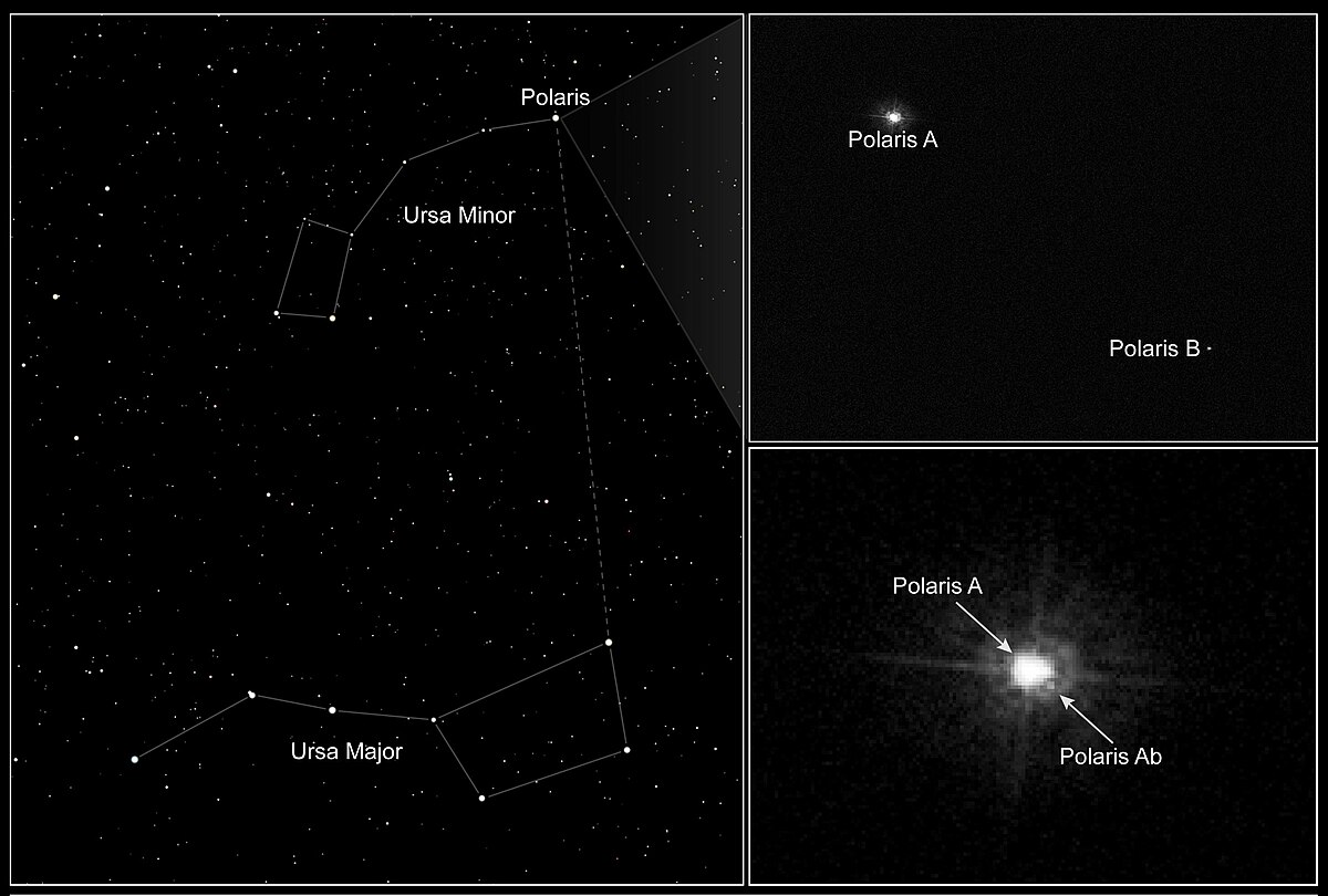
- North Celestial Pole (NCP) and South Celestial Pole (SCP): The extension of Earth’s rotation axis onto the celestial sphere. The NCP is near Polaris; the SCP has no comparably bright star.
- Polar scope: A small optical finder built into many mounts that includes a reticle to place Polaris (or a pattern of stars near the SCP) at a specific position.
- Plate solving: Software that identifies stars in an image and matches them to a celestial catalog, enabling precise measurement of where the camera is pointed.
- Cone error: The angular misalignment between your telescope’s optical axis and the mount’s DEC axis. Large cone error can complicate some alignment routines but does not change the definition of polar alignment, which is about the RA axis.
- Magnetic vs. true north: Compasses point to magnetic north, which differs from true north by your local magnetic declination. For rough setup, correct for this offset or use the Sun’s position methods in daytime alignment.
- Sidereal rate: The mount’s tracking speed that matches Earth’s rotation relative to the stars, approximately 360° per sidereal day (~23h 56m).
Knowing these basics helps you execute the step-by-step procedures in polar scope alignment, drift alignment, and plate-solve assisted alignment more efficiently.
Comparison of Polar Alignment Methods and Accuracy
There’s no single “best” technique—the right method depends on your gear, sky access, and time. Here’s how the main approaches compare.
1) Polar scope alignment
- How it works: Look through the mount’s polar scope and position Polaris (or a pattern near the SCP) on a reticle ring at a clock angle given by an app.
- Pros: Fast, no computer required, accurate enough for many setups when the reticle is calibrated.
- Cons: Requires a clear view toward the pole; reticle calibration matters; challenging in the south without bright pole stars.
- Typical accuracy: Within a few arcminutes if the reticle is well-calibrated and adjustments are smooth.
2) Drift alignment
- How it works: Observe how a star drifts in declination at strategic sky positions and adjust mount altitude/azimuth to null that drift.
- Pros: Can achieve very high precision; works anywhere in the sky and does not require seeing the pole.
- Cons: Slower learning curve; sensitive to seeing and periodic error; best done with a camera or reticle eyepiece and patience.
- Typical accuracy: Sub-arcminute alignment is realistic with careful technique.
3) Plate-solve assisted alignment
- How it works: Software captures images near the pole, plate solves, rotates RA, and computes the offset vector between the RA axis and the celestial pole.
- Pros: Fast and highly quantitative; feedback in arcminutes or arcseconds; excellent for repeatability.
- Cons: Requires a camera, computer or smart device, and compatible software; sometimes requires good star detection/sky transparency.
- Typical accuracy: Often around an arcminute or better with a capable camera and workflow.
4) Handset routines and mount modeling
- How it works: Two- or three-star alignment on the handset, then a polar alignment routine (e.g., routines that instruct you to center a star using only mount alt/az).
- Pros: Integrated into many mounts; no extra hardware; helpful if plate solving isn’t available.
- Cons: Depends on correct star centering and optical alignment; accuracy varies; some routines prefer minimal cone error.
- Typical accuracy: A few arcminutes with careful execution; can be refined with drift or plate solving.
5) Daytime rough alignment
- How it works: Use a compass and inclinometer or the Sun’s position to set RA axis altitude and azimuth roughly.
- Pros: Gets you close before dusk; useful at star parties or sites without pole visibility.
- Cons: Not sufficient for long exposures by itself; requires nighttime refinement.
- Typical accuracy: Degrees rather than arcminutes; a starting point for later fine-tuning.
In practice, many imagers combine methods: a quick polar scope alignment to start, followed by a plate-solve routine for precision, or a final drift alignment pass if ultimate accuracy is needed.
Step-by-Step Polar Scope Alignment with Polaris
Polar scopes remain popular because they’re fast and independent of computers. The key is to calibrate the reticle and place Polaris at the correct clock angle relative to the NCP.

Artist: Gn842
Calibrate the polar scope reticle
- Check orthogonality: In daylight, aim the mount roughly level and point the polar scope at a distant object. Rotate the RA axis 180°. If the object stays centered on the reticle’s center crosshair, the reticle is centered. If it arcs around the center, adjust the reticle centering screws per your mount’s manual until rotation keeps the same point centered.
- Reticle rotation alignment: Many reticles have numerals or the “Polaris circle” that must be oriented to true clock positions. The reticle should be rotated so that when Polaris is due east or west of the NCP, you can place it at the 3 or 9 o’clock positions correctly. Some mounts let you rotate the reticle; others rely on RA index marks and app guidance.
Find the current Polaris position on the reticle
- Use a polar alignment app that computes Polaris’ hour angle relative to the NCP for your location and time. Apps provide a clock-face display; you place Polaris on the reticle at that angle.
- Polaris is not exactly at the NCP; it sits roughly three-quarters of a degree away. That offset is why the reticle shows a small ring around the center.
- Ensure your smartphone time and location are accurate; enable GPS or set coordinates manually.
Position Polaris on the reticle
- Set the mount at your latitude using the altitude scale as a starting point.
- Use the azimuth knobs to aim roughly north (correcting for magnetic declination if using a compass).
- Look through the polar scope and center Polaris in the field. If you wear glasses or have difficulty focusing, adjust the diopter on the polar scope eyepiece.
- Rotate the RA axis to align the reticle’s clock orientation with the app display. Some apps also show where Polaris should be without rotating the RA; follow your reticle’s manual.
- Use the altitude and azimuth knobs to place Polaris on the small circle at the clock angle indicated by the app. Move smoothly; backlash and stiction can kick Polaris out of place if adjustments are jerky.
Refinements and tips
- Illumination: Use the built-in reticle illumination sparingly so you can see both the reticle and Polaris comfortably.
- Parallax: Keep your eye centered. If your eye moves, the apparent position of Polaris against the reticle can shift slightly.
- Southern Hemisphere: Without a bright pole star, southern reticles often depict the Octans asterism. If your reticle supports it, match the star pattern; otherwise, consider plate-solve routines which are especially helpful in the south.
- Check after loading: Heavy payloads can shift alignment as the tripod settles. After mounting your telescope and camera, recheck polar alignment.
- Refine later: A good polar scope alignment can be improved further via drift alignment or a software-assisted routine if your guiding graph suggests residual drift.
Drift Alignment for Sub-Arcminute Precision
Drift alignment is a classic technique that does not depend on seeing the pole. It measures how a star drifts in declination over time due to misalignment, and you eliminate that drift by adjusting the mount’s altitude and azimuth. It can be performed visually with a reticle eyepiece, but using a guide camera and software makes it easier to see small drifts.
Concept overview
A misaligned RA axis causes stars to slowly drift north or south in the eyepiece/camera (nullDeclination driftnull). By choosing stars in specific parts of the sky, you can isolate whether the drift comes from azimuth error or altitude error:
- Azimuth error check: Point to a star near the local meridian and near the celestial equator (declination ~0nullB0). If the star drifts north/south, adjust azimuth to minimize the drift.
- Altitude error check: Point to a star low in the east (or west) near the celestial equator. If it drifts north/south, adjust altitude to reduce the drift.
Equipment and setup
- A camera attached to your telescope or a guide scope provides a stable view and allows software-based drift analysis.
- High magnification or longer focal length makes drift easier to detect, but you’ll need to balance that against seeing and mount stability.
- Use a crosshair overlay or guider software to quantify drift direction and rate.
Step-by-step drift routine
- Rough polar alignment first: Use a polar scope or a quick plate-solve method to get close. This speeds up convergence.
- Azimuth correction:
- Choose a bright star near the meridian and near declination 0nullB0.
- Center it and observe the declination drift over 2–5 minutes (longer if needed). Ignore RA drift due to tracking error; you’re watching north/south motion.
- If the star drifts in one direction, adjust the mount’s azimuth knobs slightly to reduce the drift. Re-center and repeat until the drift is minimal.
- Altitude correction:
- Pick a star low in the eastern sky (20–30nullB0 altitude) near declination 0nullB0. Alternatively, use a western star if the east is blocked.
- Observe declination drift again. Adjust the mount’s altitude up/down to minimize the drift. Re-center and repeat.
- Iterate: Azimuth and altitude adjustments influence each other slightly; iterate between steps until both positions show negligible drift.
- Confirm: Re-test your meridian star and your low-eastern/western star to ensure both conditions are satisfied.
Practical guidance and tools
- Use guiding software: Many imagers leverage guiding tools with drift-alignment helpers. These tools can display drift rate numerically and suggest which adjustment to make.
- Give it time: Average over a couple of minutes to avoid being fooled by seeing. Sudden jumps may indicate backlash or cable tug.
- Small moves: Turn adjusters very gently; overshooting leads to a prolonged back-and-forth.
- Rebalance if needed: If the mount binds or jumps when you touch adjusters, check tripod tension and payload balance.
While plate-solve methods have streamlined alignment, drift alignment remains a robust way to reach very high precision, especially when software feedback is limited or the pole is obstructed.
Plate-Solve Polar Alignment with Cameras and Apps
Plate-solve assisted polar alignment uses your imaging or guide camera to take short exposures, identify the star field, and compute exactly where the mount is pointing. The software then quantifies the offset between your mount’s RA axis and the celestial pole and guides you through altitude and azimuth corrections in real time.
How plate-solve alignment works conceptually
- The software captures an image with the camera aligned along or near the RA axis direction.
- It plate solves the image to find precise sky coordinates (right ascension/declination) for the camera’s field.
- You then rotate the RA axis by a known amount (e.g., 60nullB0–90nullB0) while the software captures and solves another image.
- By analyzing how the star field moves relative to the RA rotation, the software computes the true direction of the RA axis and its offset from the celestial pole.
- On-screen vectors show how to move the mount’s altitude and azimuth to null the error.
Typical workflow
- Attach a camera: Use your main imaging camera or a guide camera. Ensure focus is acceptable and stars are visible.
- Start the polar alignment tool: The software will take a short exposure and solve it.
- Rotate RA: Follow prompts to rotate the RA axis by a specified angle. The tool measures the pivot geometry.
- Adjust alt/az: Use the on-screen guidance to turn your altitude and azimuth knobs. The live feedback tells you when you’re close.
- Validate: Run a verification pass, or take a short guided exposure to check star shapes. If necessary, refine with drift.

The system is powered by an ALLWEI 256 Wh lithium iron phosphate battery set up below the tripod, which is lit up in red by the mount’s power adapter. In the background is a wagon filled with extra accessories and the west facade of Memorial Library at UW-Madison.
Artist: Brainandforce
Strengths and considerations
- Speed: Many users can reach arcminute-level alignment in minutes once familiar with the process.
- Quantitative: The software reports residual error numerically, making it easy to compare sessions and diagnose issues.
- Flexibility: Works well in the Southern Hemisphere and in light-polluted skies if stars are detectable.
- Field of view: If your camera’s field of view is very small, plate solving near the pole can be trickier. A guide scope with a wider field can help.
Plate-solve polar alignment has become a go-to approach because it provides clear, actionable feedback. Even if you start with a polar scope routine, a quick plate-solve pass is an efficient way to confirm and refine your alignment before a long imaging run.
Southern Hemisphere Tips: Octans and No-Polaris Skies
Observers in the Southern Hemisphere face the challenge that there is no bright star like Polaris marking the SCP. However, reliable polar alignment is still very achievable with a mix of reference patterns and software.
Star patterns and reticles
- Some polar scopes include reticles that depict stars of the Octans constellation near the SCP. If your reticle supports this, you can align by matching the pattern and placing the SCP at the reticle’s center.
- If your reticle lacks southern references, use plate-solve tools which are particularly effective in the south.
Plate solving advantage
Plate solving is robust in the south because it does not rely on a single reference star. It identifies the entire star field and computes the SCP offset vector directly from the geometry of your RA rotation.
Workflow tips specific to the south
- Start with a rough compass/inclinometer alignment as described in daytime methods.
- Perform a plate-solve polar alignment routine. If plate solving struggles due to clouds or low star density near the pole, try a wider field optic or move slightly away from the exact pole while following the software’s instructions.
- Refine with drift alignment if your exposure goals or focal length demand sub-arcminute precision.
Field Rotation, Guiding, and Exposure Length Trade-offs
Polar alignment error produces field rotation: stars rotate around a point in your frame as the mount tracks. Guiding can keep the guide star centered, but stars farther from the guide star will still arc if the RA axis is misaligned. This is especially noticeable in wide fields or long exposures.
What determines how much field rotation you see?
- Polar alignment error (magnitude and direction): Larger misalignment yields faster rotation.
- Target position: Rotation depends on target altitude and azimuth; some parts of the sky are more sensitive to misalignment.
- Distance from the guide star: If you guide, stars far from the guide star will show more rotation than those near it.
- Exposure length and focal length: Longer exposures and longer focal lengths reveal smaller rotational arcs as visible elongation.
Practical guidelines
- For wide-field lenses (e.g., 14–50 mm) and short exposures (20–120 seconds), a modest alignment error may be tolerable, especially if you don’t guide.
- At 200–600 mm, strive for a few arcminutes or better and consider guiding. You’ll notice improvements in star roundness and consistency.
- At 800–1500 mm and beyond, aim for sub-arcminute alignment, then rely on guiding to manage mount periodic error. Shorter, more numerous subframes can also help.

He had just arrived at Greenland’s Thule Air Base on March 20 when a mechanical issue grounded the aircraft. No science flight could happen for a few days. As teams in the United States and Greenland scrambled to locate and deliver a replacement part, researchers on the ground waited. Some of them hiked to what was locally known as “the iceberg.”
The unnamed berg pictured above has been frozen in place by sea ice in North Star Bay. Harbeck shot the photograph—a composite of four 49-second images—on March 21 at about 2:30 a.m. local time. The sun never fully sets at this time of year in the Arctic, so sunlight appears on the left side of the image. Lights from Thule are visible on the right side. Look for the Milky Way (top left) and a few very faint meteors visible in the early morning sky.
Harbeck left the dock at Thule with sea ice scientist (and current IceBridge project scientist) Nathan Kurtz and a local recreation officer at about 10 p.m. From there, the group hiked 2.4 kilometers (1.5 miles) across the still-thick sea ice in weather that Harbeck called a “pleasant” minus 18 degrees Celsius (0 degrees Fahrenheit). They paused frequently on the way, and they even circled the berg to check for polar bears.
“You don’t have a sense of scale of this berg until you get up to it,” Harbeck said. “It’s about the size of my apartment building, and that’s only the part protruding from the water.” Assuming the berg is ungrounded (which is uncertain), about one-tenth of its mass is above water.
Artist: Jeremy Harbeck
The best approach is incremental: achieve good alignment using a method in methods and accuracy, take a test exposure of a few minutes, inspect star shapes across the frame, and improve alignment if you see rotation or consistent elongation. Combining a solid alignment with reliable guiding typically yields the best results.
Common Polar Alignment Mistakes and How to Fix Them
Even experienced imagers make small mistakes that undermine alignment. Here are common pitfalls and how to address them.
- Uncalibrated or off-center reticle: If your polar scope reticle isn’t centered relative to the RA axis, you can’t place Polaris correctly. Recalibrate as described in reticle calibration.
- Chasing seeing while drifting: Atmospheric turbulence makes stars wander. When doing drift alignment, average drift over time; don’t adjust for every jiggle.
- Backlash and stiction in adjusters: Sloppy bolts can spring or bind. Apply gentle, consistent pressure in one direction to take up backlash before finalizing. If adjusters stick, slightly loosen the opposite bolt before tightening the other.
- Forgetting to lock down: Some mounts have altitude/azimuth locks separate from adjusters. Once aligned, snug them carefully to avoid shifting.
- Loose tripod or ground settling: Soft ground or unbalanced payloads can cause slow shifts. Use a stable surface and check alignment after slewing to different targets.
- Ignoring cone error during handset routines: Large cone error can mislead star alignment routines. While cone error doesn’t cause field rotation directly, minimizing it helps when using handset-assisted polar alignment.
- Assuming perfect level is required: A level tripod helps adjustments behave predictably, but an equatorial mount can be polar aligned even if not perfectly level. Leveling is good practice, not a strict requirement for correctness.
- Cable drag: Cables that snag or tug can pull the system off alignment. Strain-relief your cables and verify free movement through expected slews.
Alt-Azimuth Mounts, Wedges, and Star Trackers
Portable star trackers and Schmidt-Cassegrain telescopes (SCTs) on alt-az mounts can be equipped with wedges to mimic an equatorial configuration. The goal is the same: align the rotation axis with the celestial pole to eliminate field rotation during long exposures.
Star trackers
Artist: HiyoriX
- Portable and practical: Lightweight trackers with built-in polar scopes are ideal for travel and wide-field work.
- Balance and load: Keep payload under the tracker’s rated capacity, especially at longer focal lengths. Imbalances make adjusters harder to use and increase drift.
- Method choice: A well-calibrated polar scope can be surprisingly effective. For refined results, consider a small guide camera and a plate-solve alignment routine if your tracker supports it with a computer or control unit.
Alt-az mounts on wedges
- Wedge setup: The wedge effectively tilts the alt-az mount so that its primary axis acts like the RA axis.
- Alignment process: Use the wedge’s altitude and azimuth adjusters. Many users start with a rough alignment and refine using handset routines, plate solving, or drift.
- Stability: Ensure the wedge is rigid and the bolts are snug. Flexure or slop in a wedge can degrade alignment quality even after careful adjustment.
Daytime Polar Alignment and No-Polaris Seasons
If you set up before dark, or if trees/buildings hide the pole at night, a daytime rough alignment can save time. The idea is to point the RA axis toward true north/south and set the altitude to your latitude, then refine later.
Compass and inclinometer method
- Find true north: Determine your local magnetic declination and offset your compass reading accordingly. Many map apps display magnetic and true bearings; check local values for accuracy.
- Set altitude: Use the mount’s altitude scale or a digital inclinometer to set the RA axis to your site’s latitude.
- Mark the ground: If you return to the same site often, mark tripod leg positions to speed repeatability.
Solar position method
- Use the Sun safely: Do not look through optics. Instead, use the shadow cast by the mount or a gnomon to align azimuth to the Sun’s known bearing at a specific time.
- Solar noon: At local solar noon, the Sun is due south (or due north in some latitudes). Align the RA axis along that meridian for a good azimuth starting point.
- Refine at dusk: Once stars appear, switch to plate solving or polar scope to dial in the precision you need.
Daytime methods aren’t the final word, but they put you close enough that your first nighttime alignment pass is quick and decisive.
Troubleshooting Guiding After Polar Alignment
Sometimes guiding remains unstable even after a careful polar alignment session. Use the following checks to diagnose and fix issues.
- Residual polar error: If your guiding assistant reports a significant polar alignment error, revisit a plate-solve routine or do a quick drift check.
- DEC backlash: Excessive backlash in declination can cause delayed corrections that look like drift. Balance DEC slightly to preload gears and tune guiding parameters to avoid oscillation.
- RA periodic error: Guiding in RA will still be required to correct worm periodic error. Periodic error training (if supported) and appropriate exposure/gain in your guide camera can help.
- Flexure: Differential flexure between a guide scope and the main scope can mimic drift. A rigid setup or an off-axis guider reduces this issue.
- Cable management: Tugs during slews or tracking can cause sudden deviations. Add strain relief and route cables to move freely with the mount.
- Focus and seeing: Poor guide star SNR or high seeing can lead to noisy guiding. Adjust exposure length, gain, and star selection for stable centroiding.
- Calibration matters: Calibrate guiding near declination 0nullB0 and near the meridian for the most robust solution. Recalibrate after major changes to the setup.
Frequently Asked Questions
How accurate does polar alignment need to be for deep-sky imaging?
It depends on focal length, exposure time, and your tolerance for slight elongation. For wide-field lenses and short exposures, a few arcminutes may be fine. For long focal lengths and multi-minute subs, aim for residual polar error around a few arcminutes or better, and for demanding projects target sub-arcminute. Use plate-solve tools for speed, and refine with drift alignment if you need even tighter results.
Do I need to level my tripod perfectly to get a good polar alignment?
A level tripod makes altitude and azimuth adjustments more predictable and repeatable, but it’s not strictly required for a correct polar alignment. An equatorial mount can be polar aligned even if the tripod is slightly off level because the goal is the RA axis direction in space, not the mount’s relation to gravity. That said, leveling is still good practice—it reduces the chance of slippage and makes the process less confusing.
Final Thoughts on Mastering Polar Alignment for Astrophotography
Polar alignment is the foundation that unlocks longer exposures, tighter stars, and smoother guiding. Whether you prefer a well-calibrated polar scope, the time-tested precision of drift alignment, or the speed and quantitative feedback of plate-solve workflows, the essential idea remains the same: align your RA axis with the celestial pole as accurately as your project demands.
A practical approach is iterative. Begin with a quick technique that gets you close, run a test exposure, and then refine. Over time, you’ll develop a personal routine that balances speed with the precision needed for your focal length and sky conditions. With a solid polar alignment and a stable, well-balanced mount, everything else in your imaging workflow—from guiding to mosaic building—becomes easier.
If you found this deep dive useful, consider subscribing to our newsletter to get weekly, research-backed guides on astrophotography techniques, gear optimization, and night-sky science. Explore more topics in our archive and come back next week as we continue rotating through astronomy themes with fresh, complementary perspectives.