
Table of Contents
- What Is Numerical Aperture in a Microscope?
- How Resolution Is Defined: Abbe, Rayleigh, Sparrow
- NA, Wavelength, and Diffraction-Limited Resolution
- Magnification vs Useful Magnification: Avoiding Empty Magnification
- Contrast, Illumination, and Coherence: Why Lighting Controls Detail
- Objectives, Condensers, and Immersion Media: Matching the Optical Train
- Field of View, Depth of Field, and Digital Sampling (Nyquist)
- Calibration, Measurement, and Common Pitfalls to Avoid
- Frequently Asked Questions
- Final Thoughts on Choosing the Right Numerical Aperture and Magnification
What Is Numerical Aperture in a Microscope?
Numerical aperture (NA) is the core performance number that determines a microscope objective’s ability to gather light and resolve fine detail. It is defined by the geometry of the objective and the refractive index of the medium between the front lens and the specimen. Formally:
NA = n × sin(θ)
where n is the refractive index of the immersion medium (air, water, glycerol, or oil) and θ is the half-angle of the widest cone of light that can enter (or exit) the lens. A higher NA corresponds to a wider acceptance cone and, consequently, better resolving power and light-gathering capability.
Three immediate implications fall out of this definition:
- NA depends on immersion medium. Since
sin(θ)cannot exceed 1, the upper bound of NA is set by n. With air (n ≈ 1.00), practical NA tops out near ~0.95; with immersion oil (n ≈ 1.515), NA values around ~1.3–1.4 are commonly encountered in high-end oil-immersion objectives. - NA measures both resolution potential and brightness. For a given specimen and illumination, an objective with larger NA collects more diffracted light, increasing image contrast at higher spatial frequencies and transmitting a brighter image to the detector or eye.
- NA is separate from magnification. Magnification alone does not guarantee detail; useful magnification is capped by resolution, which is tied directly to NA and wavelength.
It is also common to reference the condenser NA. In transmitted-light brightfield, the condenser projects an illumination cone through the specimen. To reach the objective’s full resolving power, the condenser NA should typically match or slightly exceed the objective NA. If your objective is NA 0.95 but your condenser is stopped down to 0.3, the illumination cone is too narrow to deliver the specimen’s highest spatial frequencies to the objective, capping resolution and contrast.
Finally, NA is not a linear measure of performance. Many improvements—resolution, light throughput, and axial sectioning—scale more strongly than linearly with NA. This is why moving from NA 0.65 to NA 0.85 can feel like a transformative upgrade, even if the objective’s nominal magnification stays the same.
How Resolution Is Defined: Abbe, Rayleigh, Sparrow
In brightfield, the ultimate limit to fine detail is governed by diffraction, not simply by lens perfection. Several closely related criteria are commonly used to quantify resolution. While the differences are subtle, being precise about them helps you compare claims and choose the right optics.
Abbe’s Criterion (periodic structures)
Abbe framed resolution in terms of the ability to transfer spatial frequencies from the specimen to the image. For periodic structures (e.g., line gratings), the minimum resolvable period d is approximately:
d ≈ λ / (2 × NA)
where λ is the imaging wavelength. This expression emphasizes the role of the diffraction orders captured by the objective. If the objective and illumination together cannot pass the necessary diffracted orders, the periodic pattern washes out.
Rayleigh Criterion (point objects)
The Rayleigh criterion uses the intensity distribution of an Airy pattern produced by a point source or a very small object. Two point sources are said to be just resolvable when the peak of one Airy disk coincides with the first minimum of the other. The lateral resolution (distance between point centers) is approximately:
d ≈ 0.61 × λ / NA
This is the most often quoted value because many biological and materials samples can be approximated locally as point-like features embedded in broader structure.
Sparrow Criterion (contrast vanishes)
Sparrow’s criterion defines the separation where the central dip between two point images disappears, leading to a single flat-topped profile. This leads to a slightly smaller number than Rayleigh (often cited near ~0.47 × λ / NA for incoherent imaging). It is more theoretical than practical for everyday microscopy, but you may see it in textbooks and optical design notes.
Lateral vs Axial Resolution
Lateral (xy) resolution is defined in the specimen plane. Axial (z) resolution quantifies how well two features can be separated along the optical axis. Axial resolution scales more steeply with NA; a commonly used approximation for widefield (incoherent) axial resolution is:
Δz ∝ n × λ / NA²
where n is the refractive index of the immersion medium. Because of the 1/NA² dependence, high-NA objectives improve sectioning substantially in the axial direction even as depth of field becomes shallower. For practical comparisons in brightfield, knowing that axial resolution tightens approximately with the square of NA is often sufficient.
Key takeaway: For incoherent widefield imaging, lateral resolution scales roughly as
λ / NAwhile axial resolution scales roughly asλ / NA². Higher NA and shorter wavelengths both improve resolution.
These criteria all describe the same underlying physics: diffraction sets a hard ceiling on spatial detail. Differences among Abbe, Rayleigh, and Sparrow reflect how we pose the “just resolved” question more than any disagreement about the optics.
NA, Wavelength, and Diffraction-Limited Resolution
Understanding the interplay between NA and wavelength is the foundation for predicting what your microscope can actually show. Because resolution criteria are proportional to λ/NA, you can reason about trade-offs as follows:
- Shorter wavelengths resolve finer detail. Blue light (e.g., ~450 nm) yields better resolution than green (~550 nm) or red (~630 nm), all else equal.
- Higher NA resolves finer detail. Increasing NA from 0.65 to 0.95 materially improves both the finest resolvable spacing and the contrast at moderately high spatial frequencies.
- The condenser NA matters in transmitted light. To realize the objective’s theoretical resolution in brightfield, the illumination cone provided by the condenser should approach the objective NA. Underfilling the condenser aperture limits the range of diffracted orders reaching the objective.
Consider a concrete comparison using Rayleigh’s lateral criterion with λ ≈ 550 nm (green, convenient for visual observation):
- NA 0.65 objective:
d ≈ 0.61 × 550 nm / 0.65 ≈ 516 nm - NA 0.95 objective:
d ≈ 0.61 × 550 nm / 0.95 ≈ 353 nm
This rough calculation shows the NA 0.95 lens can separate details roughly 30–35% smaller than the NA 0.65 lens under the same wavelength. The improvement is immediately visible in fine texture and edge sharpness, provided the illumination, sample, and detection chain do not introduce additional limits.
What about refractive index mismatch?
In high-NA imaging, index mismatch between immersion medium, cover glass, and mounting media can introduce spherical aberration, degrading contrast and effective resolution. Typical coverslips are designed around ~0.17 mm thickness (often labeled #1.5). Many high-NA objectives specify a correction for this thickness; some include a correction collar to tune for small deviations. If the sample requires a different medium (e.g., water), a water-immersion objective helps maintain performance by keeping n and dispersion closer to design values.
Resolution is not only about the smallest spacing
Resolution criteria give a threshold for “just resolved,” but image quality across the whole frequency spectrum is captured by the modulation transfer function (MTF), which describes how contrast at different spatial frequencies transfers from object to image. Objectives with higher NA usually preserve contrast better into higher frequencies, but aberrations, sample scattering, and illumination coherence can all lower MTF even if the nominal Rayleigh number looks the same.
In practice, to benefit fully from a higher NA or shorter wavelength, you should also consider illumination quality (see Contrast and Illumination), sample preparation and refractive index matching (see Objectives and Immersion), and proper sampling on your camera (see Digital Sampling).
Magnification vs Useful Magnification: Avoiding Empty Magnification
Magnification describes how large an image appears, not how much detail it contains. The most important concept for practical microscopy is useful magnification—the range of total magnification that displays the detail actually resolved by the optics without merely enlarging blur.
Total magnification
The total optical magnification for visual observation is approximately:
M_total = M_objective × M_eyepiece × M_intermediate
where M_intermediate is any relay magnification (e.g., tube lens factors in infinity-corrected systems or post-objective magnifiers). For camera-based imaging, what matters is the effective pixel size in the specimen plane (see Sampling), which depends on total system magnification from specimen to sensor.
Useful magnification rule-of-thumb
Because resolution is limited by diffraction (and aberrations), a widely used rule-of-thumb for visual observation is:
Useful magnification ≈ 500× to 1000× NA
For example, with an NA 0.65 objective, useful magnification typically lies between roughly 325× and 650× for visual work. Below this range, you might not fully appreciate the resolved detail; above it, you are likely entering empty magnification, where the image gets larger but no new information appears. For digital imaging, the sampling requirement provides a similar constraint in terms of pixels per resolution element.
Empty magnification and digital zoom
Empty magnification also occurs when you resize images or increase display scaling without increasing optical or sensor sampling. Digital zoom after acquisition is merely interpolation—no new spatial frequency content is acquired. If you need to show more detail, increase NA or improve your sampling at the time of capture rather than magnifying a low-resolution image.
Balancing magnification, NA, and working distance
Objectives with higher magnification do not always have higher NA. A high-NA 40× objective may resolve more than a lower-NA 60×. When choosing lenses, compare NA first, then magnification, while also checking factors like working distance and cover glass correction (see Objectives and Immersion). If you require room for microtools or thicker samples, you may prefer a slightly lower NA with longer working distance, accepting a resolution trade-off.
Contrast, Illumination, and Coherence: Why Lighting Controls Detail
Even when NA and magnification are correctly chosen, illumination critically shapes what you can see. Brightness, uniformity, angular spread, and coherence all affect how sample information transfers to the image. Well-controlled illumination does not violate the diffraction limit, but it can help you reach it and present resolvable structure with higher contrast.
Illumination NA and the condenser
In transmitted-light brightfield, the condenser sets the illumination cone. If the condenser aperture is stopped down too far, high-angle diffracted rays from the specimen do not interfere to form high-frequency contrast in the image. If you want to exploit an objective’s full resolution, the condenser NA should be opened to approximately match the objective NA. Conversely, stopping down the condenser (reducing illumination NA) increases image contrast at low magnification but at the cost of resolving power and depth cues.
Köhler illumination (concepts, not steps)
Köhler illumination is an optical configuration that provides uniform, glare-free illumination with adjustable aperture and field stops. Conceptually, it images the light source onto the condenser’s aperture (controlling angular illumination) and the field diaphragm onto the specimen plane (controlling the illuminated area). When implemented, it stabilizes brightness and contrast across the field and helps you set illumination NA independent of field size. This configuration supports diffraction-limited performance across the view and is considered a best practice for brightfield and many contrast techniques.

Coherence and the σ parameter
Illumination coherence describes how correlated light rays are across the beam. In microscopy, a practical measure is σ (sigma), the ratio of illumination NA to objective NA: σ = NA_illum / NA_obj. In brightfield:
- Lower σ (more coherent) can improve fine detail visibility in some periodic structures but may introduce ringing or artifacts, and is more sensitive to dust and imperfections.
- Higher σ (more incoherent) tends to smooth out artifacts and improve overall contrast uniformity but may slightly reduce the contrast of the very highest spatial frequencies.
Broad-spectrum, extended sources (e.g., LEDs in a diffused Köhler setup) typically provide partially incoherent illumination that strikes a good balance for general brightfield. For Abbe-limited detail, a well-matched σ with condenser NA near the objective’s NA delivers robust high-frequency transfer.
Contrast methods do not change the diffraction limit
Phase contrast and differential interference contrast (DIC) are powerful methods for enhancing visibility of low-contrast, transparent structures. They convert phase variations in the specimen into intensity differences, dramatically improving contrast. However, they do not surpass the diffraction limit set by λ/NA. They can make features near the limit easier to see, but the underlying smallest resolvable spacing remains governed by the optics and wavelength.
Similarly, simple techniques like adjusting the condenser aperture, using oblique illumination, or applying polarization can change contrast and emphasize edges, but they do not change the fundamental resolution criteria described in How Resolution Is Defined.
Objectives, Condensers, and Immersion Media: Matching the Optical Train
Your microscope’s performance is only as strong as the least suitable component in the optical path. Objectives, condensers, and immersion media must work together consistently for you to realize the benefits of high NA and appropriate magnification.
Objectives: the main performance drivers
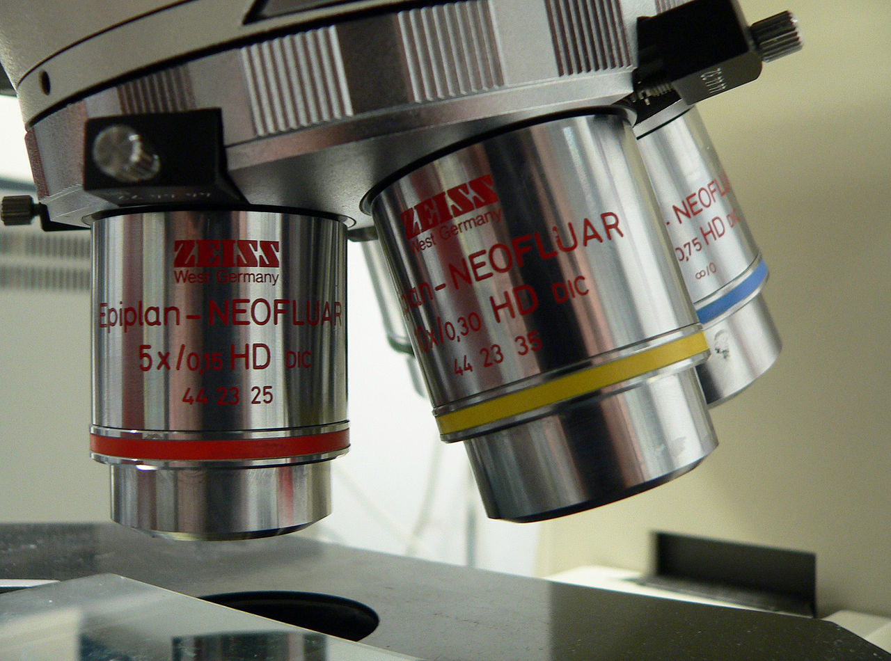
Objective specifications typically include magnification, NA, working distance, and cover glass correction. Common considerations:
www.micro-shop.zeiss.com/
- NA first, then magnification: If your primary goal is fine detail, prioritize higher NA even if magnification is similar to alternatives. This aligns with the principles in Useful Magnification.
- Plan vs achromat: Plan objectives provide flatter fields (reduced field curvature) across the view, helpful for imaging or wide-field observation. Achromats correct two wavelengths for color and are common in educational scopes. Higher-grade apochromats correct more wavelengths and often offer higher NA.
- Cover glass correction: Many high-NA objectives are designed for #1.5 coverslips (~0.17 mm). Mismatch introduces spherical aberration. Objectives with correction collars allow fine tuning for slightly different thicknesses and media.
- Working distance: Higher NA usually shortens working distance. If you need space for micro-manipulation or thick samples, you may trade some NA for working distance, acknowledging the resolution consequences outlined in NA and Resolution.
Condensers: delivering the right illumination cone
In transmitted light, the condenser’s NA and its diaphragms strongly influence achievable resolution and field uniformity:
- NA matching: To reach an objective’s full NA in brightfield, the condenser aperture should be opened to approximately the objective’s NA. Underfilling lowers effective resolution.
- Field diaphragm: Setting the field diaphragm to slightly underfill the field of view improves contrast and reduces stray light without changing resolution. This is inherent to the Köhler concept mentioned in Illumination.
- Special contrast condensers: Phase contrast and DIC use specialized annuli or prisms. They change the phase or differential gradients in the specimen into intensity variations but do not raise the diffraction ceiling.
Immersion media: air, water, glycerol, oil
Because NA = n × sin(θ), immersion media with higher refractive index enable higher NA. Practical aspects to keep in mind:
- Air (n ≈ 1.00): Convenient and clean, but NA is capped around ~0.95 and spherical aberration is sensitive to cover thickness at high NA.
- Water (n ≈ 1.33): Supports NA above 1.0 and is more index-matched to aqueous samples, reducing spherical aberration in thick or live specimens.
- Glycerol (n ≈ 1.47): A compromise medium useful when sample mounting media have intermediate index; helps mitigate mismatch across thicker specimens.
- Oil (n ≈ 1.515): Highest practical NA in many widefield systems (~1.3–1.4), excellent for thin specimens with cover glass of correct thickness.
Using an immersion objective without the appropriate medium (or vice versa) severely compromises performance. Similarly, high-NA transmitted-light work sometimes benefits from immersion condensers, which increase the condenser NA by filling the gap between top lens and slide with a medium. This can be advantageous when pushing the limits of brightfield resolution, though it adds handling complexity.
Field of View, Depth of Field, and Digital Sampling (Nyquist)
Resolution tells you the smallest feature you can distinguish, but image utility also depends on how much of the specimen you see at once, how much of it is in focus, and whether your detector samples the optical information adequately. These trade-offs are central to camera selection, objective choice, and display scaling.
Field of view (FOV)
For visual observation, the field of view diameter in the specimen plane is approximately set by the eyepiece’s field number (FN) and the objective magnification:
FOV_diameter ≈ FN / M_objective
For example, with FN 20 mm and a 40× objective, the specimen-plane FOV diameter is roughly 0.5 mm. For camera systems, the FOV depends on the sensor size and the total optical magnification from specimen to sensor. Larger sensors or lower magnification produce wider fields; higher magnification or smaller sensors crop into the specimen.
Depth of field (DOF) vs depth of focus
Depth of field describes the axial range in the object space over which detail appears acceptably sharp. Depth of focus (note the different word) refers to the permissible shift in the image space (near the sensor or eyepiece) while maintaining acceptable sharpness. As NA increases, depth of field decreases strongly—approximately with the inverse square of NA. Qualitatively:
- Higher NA → shallower DOF. This is an intrinsic consequence of tighter focusing and larger cones of acceptance.
- Shorter wavelength → shallower DOF. Blue light sharpens focus but also reduces the axial tolerance band.
- Sample thickness and refractive mismatch matter. In thick or inhomogeneous specimens, refractive index variations broaden the effective PSF, reducing usable DOF and contrast.
These relationships mean you should expect to refocus more frequently and use thinner sections as NA increases, which is consistent with the resolution scaling discussed in Resolution Criteria.
Digital sampling and the Nyquist criterion
Camera pixels must sample the optical image finely enough to capture the highest spatial frequencies delivered by the objective. The Nyquist–Shannon sampling theorem requires at least two samples per period of the highest frequency to avoid aliasing. In microscopy this is commonly phrased as: sample each diffraction-limited spot with at least 2 pixels across its full width, and preferably 2–3 for robust measurements.
If we use the Rayleigh lateral resolution d ≈ 0.61 × λ / NA as the characteristic feature size, then a reasonable sampling guideline for the effective pixel size at the specimen is:
p_effective ≤ d / 2 ≈ (0.61 × λ) / (2 × NA) ≈ 0.305 × λ / NA
Many practitioners aim for ~2.3–3 pixels across the diffraction-limited spot for better quantitation, implying slightly smaller p_effective than the strict Nyquist limit.
To compute p_effective, divide the physical camera pixel size by the total magnification from the specimen to the sensor (including tube lens and any intermediate optics). For example, with 6.5 µm pixels and 60× total magnification to the sensor, p_effective ≈ 108 nm per pixel. If your objective is NA 1.3 at 550 nm, d ≈ 258 nm, so Nyquist would suggest p_effective ≤ ~129 nm. The 108 nm/pixel sampling is adequate and provides some oversampling headroom.
Conversely, if the effective pixel size is much larger than d/2, fine detail may be aliased or lost, regardless of high NA. This emphasizes the role of the detector in the performance chain: optical resolution can be squandered by under-sampling, much as it can be squandered by excess magnification in visual observation (see Empty Magnification).
Balancing FOV, DOF, and sampling
Trade-offs are inevitable:
- Wider FOV vs sampling density: A large sensor can collect a wide field without reducing sampling density, but at higher cost. Alternatively, lower magnification widens the field but coarsens the effective pixel size unless the pixel pitch is small.
- High NA vs DOF: Increasing NA improves resolution but narrows DOF. For samples with surface roughness or thickness, you may accept slightly lower NA or use techniques like focus stacking (where appropriate for non-live, non-time-sensitive imaging) to visualize structure across depths.
- Spectral band choice: Imaging at shorter wavelengths improves resolution and may support slightly lower magnification for the same information content, but can reduce DOF and alter contrast. This should be weighed against sample properties and illuminant availability.
Calibration, Measurement, and Common Pitfalls to Avoid
Accurate interpretation of microscope images depends not just on optical limits but on reliable scale and consistent imaging geometry. While exact procedures vary by instrument, the following concepts help you avoid common mistakes and get the most from the NA–resolution–magnification triangle.
Spatial calibration with known references
To turn pixels into micrometers for measurements, you must calibrate the system using a reference of known dimension. Conceptually, this involves imaging a calibration slide (e.g., a stage micrometer with precisely spaced rulings) and determining the pixel-to-micrometer conversion for the specific optical configuration (objective, tube lens, any intermediate magnification, camera). Because this ratio changes with magnification and optical adapters, each configuration needs its own calibration. When you later change objectives or add/remove intermediate optics, re-check your calibration.
Parfocality and consistency across objectives
Microscopes are designed so that objectives are parfocal—switching them should leave the specimen nearly in focus. If switching causes large focus shifts, the imaging geometry may be misaligned. This can indirectly affect measurements and perceived resolution, especially with shallow depth of field at high NA. Adjusting the viewing diopters correctly for your eyes helps ensure you are not compensating optical misalignments with eye strain.
Cover glass thickness and spherical aberration
High-NA lenses are sensitive to the thickness and refractive index of the cover glass and mounting medium. A mismatch introduces spherical aberration that spreads the point spread function, reducing contrast and effective resolution. If you often work with nonstandard covers (or no coverslip), consider objectives designed for such conditions (e.g., water-immersion with adjustable collar), as discussed in Objectives and Immersion Media.
Condenser alignment and aperture setting
Underfilled or decentered condensers limit illumination NA and inject asymmetries, reducing high-frequency contrast. A correctly configured condenser enables the objective to reach the diffraction-limited performance predicted by NA–wavelength relations. The field diaphragm should trim the illuminated area to just within the field of view to minimize stray light without sacrificing resolution.
Excess magnification and display scaling
As emphasized in Magnification vs Useful Magnification, exceeding useful magnification merely enlarges blur. On monitors, displaying images at very high zoom factors can give a false sense of detail. Always relate what you see to the system’s calibrated scale and sampling.
SNR and exposure
Resolution is only meaningful if contrast rises above noise. High-NA systems collect more light, but short exposures or dim illumination lower the signal-to-noise ratio (SNR), masking high-frequency detail even when it is, in principle, resolvable. Average multiple frames (where motion permits), increase illumination within sample-safe limits, or adjust detection sensitivity to maintain adequate SNR so that the theoretical resolution manifests in practice.
Common misconceptions to avoid
- “Higher magnification means higher resolution.” False. NA and wavelength set resolution; magnification only scales the image.
- “Phase/DIC increases resolution.” Not in the diffraction-limited sense. They enhance contrast of existing detail.
- “Any camera can capture any resolution.” Only if pixel sampling meets the Nyquist guideline given in Digital Sampling.
- “All high-NA lenses perform the same on any sample.” Sample thickness, refractive index, and coverslip corrections matter, as described under Immersion and Corrections.
Frequently Asked Questions
Is a higher numerical aperture always better?
Higher NA increases resolving power and light collection, which is advantageous for revealing fine structure. However, higher NA also shortens working distance and depth of field, and increases sensitivity to cover glass thickness and refractive index mismatch. For thin, well-prepared specimens where maximum detail is the priority, higher NA is preferred. For thick samples, limited clearance, or when greater depth is desired, a slightly lower NA may be the more practical choice. The right answer depends on your specimen and imaging goals, not on NA alone.
How do wavelength and filters affect resolution?
Resolution improves at shorter wavelengths because the diffraction-limited spacing scales with λ/NA (see NA–Wavelength–Resolution). Using a blue or green band can reveal finer detail than red, all else equal. However, shorter wavelengths may also reduce depth of field and alter contrast due to sample absorption or scattering. Filters that narrow the spectral band can improve image sharpness by reducing chromatic blur and improving MTF consistency across the field, but they cannot overcome the fundamental diffraction limit set by the chosen λ and NA.
Final Thoughts on Choosing the Right Numerical Aperture and Magnification
To get the sharpest, most informative images from your microscope, concentrate first on the physics that governs detail and only second on how large the image appears. Numerical aperture and wavelength set the resolution envelope: lateral detail scales roughly with λ/NA while axial sectioning tightens with λ/NA². Within that envelope, thoughtful choices about illumination (condenser NA, uniformity, and coherence), immersion media and cover glass correction, and appropriate sampling on the camera will determine how much of the available optical performance you actually realize.
Once your NA and wavelength choices are appropriate for your specimen, choose magnification so that you are in the useful magnification range, not the empty magnification zone where the image only gets bigger without revealing new information. For visual observation, the 500–1000× NA guideline is a reliable compass; for digital imaging, ensure the effective pixel size meets the Nyquist sampling requirement relative to your optical resolution. Coordinate all elements—objective, condenser, immersion medium, and detector—so that each supports the same performance goal.
Remember these practical checkpoints as you plan or troubleshoot an imaging session:
- Match condenser NA to objective NA in brightfield to avoid under-illumination of high spatial frequencies.
- Use immersion media and cover glasses consistent with the objective’s design to limit spherical aberration.
- Verify spatial calibration with a known reference whenever you change magnification or optical adapters.
- Confirm camera sampling meets or exceeds the Nyquist guideline for your objective’s NA and chosen wavelength.
By grounding your decisions in these fundamentals, you will make meaningful, repeatable improvements to image quality—improvements that persist regardless of camera model, user, or specimen. If you found this exploration useful, consider subscribing to our newsletter for future articles on optical performance, contrast methods, and practical microscopy techniques, and explore related topics like illumination control, objective selection, and contrast enhancement to deepen your toolkit.


