Table of Contents
- What Are Brightfield, Darkfield, Phase Contrast, and DIC Microscopy?
- How Optical Contrast Works in Light Microscopy
- Brightfield Microscopy: Principle, Setup, and Best Uses
- Darkfield Microscopy: High-Contrast Edges and Small Particles
- Phase Contrast Microscopy: Visualizing Transparent Cells Without Stain
- Differential Interference Contrast (DIC): Gradient Contrast and Pseudo‑Relief
- Choosing Between Brightfield, Darkfield, Phase Contrast, and DIC
- Practical Setup and Alignment Essentials
- Interpreting Images: Artifacts and Quantitative Limits
- Advanced Variations: Oblique, Rheinberg, and Hoffman Modulation Contrast
- Frequently Asked Questions
- Final Thoughts on Choosing the Right Optical Contrast for Light Microscopy
What Are Brightfield, Darkfield, Phase Contrast, and DIC Microscopy?
Most biological and many materials specimens are largely transparent when viewed under a light microscope. Without a way to convert subtle differences in refractive index or thickness into visible intensity changes, a clear cell on a clear background can be almost invisible. That is the central problem optical contrast methods solve. Four of the most widely used techniques in transmitted light microscopy—brightfield, darkfield, phase contrast, and Differential Interference Contrast (DIC)—each approach this problem differently. They vary in optical components, the physics of contrast generation, and the types of specimens they serve best.
This article provides a practical, technically accurate guide to these contrast methods. You will learn what each technique does, how it forms an image, what kinds of samples it suits, and what limitations or artifacts to expect. If you are choosing a microscope configuration or interpreting images, the distinctions here will help you choose the right tool and read your images correctly. We will not focus on magnification or numerical aperture except where they directly influence contrast; the emphasis is on the contrast mechanism and real‑world use.
At a glance:
- Brightfield: Standard illumination; best with stained or intrinsically absorbing/scattering specimens; broad utility but poor for live, transparent samples.
- Darkfield: Blocks direct light so only scattered light forms the image; excels at highlighting edges and tiny particles; sensitive to cleanliness and alignment.
- Phase Contrast: Converts specimen‑induced phase shifts into intensity differences using a phase ring and annulus; great for live, thin, transparent samples; produces halos and shade‑off.
- DIC: Uses polarized light and interference between sheared beams; emphasizes optical path length gradients; crisp, relief‑like images with directional shading; sensitive to birefringence and requires matched components.
If you are new to these ideas, start with How Optical Contrast Works. If you already understand the fundamentals, jump directly to a method of interest—say, Darkfield for particle detection or Phase Contrast for live cells—or to the practical Choosing Between Methods section.
How Optical Contrast Works in Light Microscopy
In bright transmitted light, a specimen modifies the light that passes through it in two principal ways:
- Amplitude effects: Absorption or scattering reduces the amplitude of the transmitted wave. This leads to intensity differences directly visible in brightfield.
- Phase effects: Changes in optical path length shift the phase of the wave without necessarily changing its amplitude. A pure phase object can be nearly invisible in brightfield but can be made visible by interference‑based techniques.
The optical path length (OPL) through a uniform region is approximately the product of the refractive index and the physical thickness: OPL ≈ n × t (for uniform n and t along the ray). Variations in OPL across the field shift the phase of the transmitted wavefront. Ordinarily, a camera measures intensity, not phase. To see phase variations, a microscope employs strategies that transform phase information into intensity variations.
Each contrast method manipulates the illumination and/or the imaging path to emphasize certain components of the light field:

Attribution: Egelberg
- Brightfield relies on absorption and scattering. It makes amplitude differences visible. Stains or pigments are commonly used to enhance amplitude contrast when natural contrast is low.
- Darkfield blocks unscattered (direct) rays and collects only light that the specimen has scattered into the objective’s acceptance cone. Small features that scatter light strongly become bright against a dark background.
- Phase contrast introduces a controlled phase shift to the background (surround) light and attenuates it using a phase ring in the objective, so that interference with the diffracted light converts phase shifts to intensity differences.
- DIC (using Nomarski or Wollaston prisms with polarizers) splits the beam into two laterally sheared, orthogonally polarized components that pass through slightly different regions of the specimen. Recombination with a set bias retardation emphasizes the spatial gradient of OPL along the shear direction.
Because these approaches privilege different parts of the light field (direct vs scattered, uniform vs gradient), they also emphasize different sample features. For example, darkfield highlights edges and small particulates, phase contrast emphasizes overall cellular interiors but with halos, and DIC produces crisp edge gradients with a pseudo‑3D appearance but can obscure uniform regions.
Key idea: Brightfield visualizes amplitude differences; phase contrast and DIC visualize phase‑related differences by controlled interference; darkfield visualizes scattered light only.
Contrast methods interact tightly with objective and condenser numerical apertures (NAs), but the essence remains: you choose the illumination geometry and optical elements that best translate your specimen’s optical properties into differences your detector can see. When in doubt, revisit these fundamentals and the relationships outlined here before choosing among brightfield, darkfield, phase contrast, and DIC.
Brightfield Microscopy: Principle, Setup, and Best Uses
Brightfield microscopy is the foundational mode of transmitted light imaging. White or monochromatic light uniformly illuminates the specimen. The image forms from differences in transmitted intensity: regions that absorb more appear darker; regions that scatter light out of the imaging path also appear darker because less light reaches the image plane.
How brightfield produces contrast
In brightfield, contrast arises when the amplitude of the transmitted wave is reduced relative to the background. The causes include:
- Absorption: Dyes and pigments selectively absorb wavelengths, reducing transmitted intensity. This is the typical approach for histological sections and stained biological samples.
- Scattering: Irregularities, particles, or roughness scatter light out of the imaging path, reducing detected intensity. Thick or heterogeneous materials can show contrast even without absorption.
- Reflection and refraction losses: Interfaces and refractive index mismatches can divert light, indirectly producing darkening.
For unstained, transparent biological cells with refractive indices close to the surrounding medium, absorption is minimal and scattering is weak for low spatial frequencies. As a result, pure brightfield images can look flat and low contrast. That limitation motivates phase contrast and DIC for live cell imaging.
Illumination and alignment considerations
Brightfield benefits strongly from proper illumination geometry. The conventional alignment target is often called Köhler illumination, where the source is imaged at the condenser aperture and the field diaphragm is conjugate to the specimen plane. While step‑by‑step procedures vary by instrument, conceptually you adjust the condenser and diaphragms so that:
- The specimen is evenly illuminated across the field.
- The condenser aperture is set to a fraction of the objective NA to balance resolution, contrast, and depth of field.
- Stray light is minimized by appropriate diaphragm settings.
Even without procedural details, remembering that brightfield is sensitive to illumination uniformity helps explain why proper alignment matters. Uneven illumination can masquerade as specimen contrast and mislead interpretations.
When brightfield excels
- Stained thin sections of tissues or materials with intrinsic pigments.
- Printed features or patterned films with strong absorption at the imaging wavelength.
- Documentation and education where color information from stains is essential.
- General surveys before switching to specialized contrast to explore a field of view.
Limitations and artifacts
- Poor contrast for unstained, phase‑dominant specimens (live cells in aqueous media).
- Apparent features from nonuniform illumination or dust can be mistaken for sample details.
- Glare and flare from bright background may obscure fine details; closing the condenser aperture too much increases contrast but reduces resolution and can introduce diffraction artifacts.
When brightfield reaches its limits on transparent samples, the next logical steps are phase contrast for simple, halo‑rich visualization or DIC for higher‑NA, relief‑like gradient contrast. For particle highlighting or edge emphasis, consider darkfield.
Darkfield Microscopy: High-Contrast Edges and Small Particles
Darkfield microscopy in transmitted light creates a dark background by blocking direct illumination from entering the objective. Only light that the specimen scatters into the objective is imaged. The result is a striking, high‑contrast rendering of edges, fine filaments, and small particles that might be invisible in brightfield.
How darkfield works
In a typical transmitted darkfield setup, the condenser forms a hollow cone of light with a central stop that excludes on‑axis rays. If no specimen is present, the cone passes around the objective’s front aperture and no light enters the objective—yielding a dark field. When the specimen scatters some of the oblique illumination into the objective’s acceptance angle, that scattered light forms bright features on a dark background.
A useful guideline is that the condenser’s effective numerical aperture must exceed the objective’s NA for good darkfield. This geometry helps ensure that directly transmitted light (which would brighten the background) misses the objective while scattered light from the specimen can still be captured.
What darkfield reveals
- Edges and boundaries: Abrupt refractive index changes scatter strongly, lighting up contours.
- Small particulates: Particles substantially below the diffraction limit appear as bright points; while not resolved in size, their presence and motion are evident.
- Fine filaments and surface textures: Structures like thin fibers can produce strong scattered signals.

Attribution: Dr Graham Beards
Because darkfield images only scattered light, uniform regions (even with different thickness) remain dark. This is a strength when you want to suppress background and emphasize features that scatter.
Strengths
- Excellent signal‑to‑background for scatterers; backgrounds can be near black under good alignment.
- Reveals sub‑resolution particles as blinking or moving bright spots, aiding detection and tracking (though not size measurement beyond qualitative indications).
- Useful for live microorganism motility when labeling is undesirable.
Limitations and practical cautions
- Cleanliness is critical: Dust or scratches scatter and produce distracting background speckles.
- Specimen thickness: Thick or highly scattering samples generate multiple scattering and glare, washing out contrast.
- Sensitivity to alignment: Misalignment lets direct light leak into the objective, brightening the background.
- Objective compatibility: High‑NA objectives may require special darkfield condensers to maintain the hollow cone geometry. For oil‑immersion objectives, matching condensers are typically needed to keep the geometry dark.
- No intrinsic grayscale proportionality: Intensity is related to scattering strength, which depends on refractive index contrasts, size, and illumination geometry; it is not directly proportional to thickness or mass.
When your goal is to visualize edges, minute particulates, or filamentary structures with strong scattering, darkfield is often the first choice. For more balanced renderings of transparent interiors (e.g., cell organelles), moving to phase contrast or DIC is typically better.
Phase Contrast Microscopy: Visualizing Transparent Cells Without Stain
Phase contrast microscopy is a classic technique for imaging transparent specimens such as living cells in culture. It converts specimen‑induced phase shifts—arising from refractive index and thickness differences—into intensity contrast, without the need for stains that might alter physiology.
The optical principle
A wave emerging from the specimen can be modeled as the sum of an undeviated (surround) component and diffracted components produced by the specimen’s spatial structure. In phase contrast, a ring‑shaped illumination annulus in the condenser forms a matching ring of light at the back focal plane of the objective. The objective contains a phase ring—a ring‑shaped region with a thin film that imposes a fixed phase shift (commonly a quarter‑wavelength, i.e., 90 degrees) and typically attenuates the surround light relative to the diffracted light.
When the surround and diffracted components interfere at the image plane, the fixed phase shift ensures that phase variations introduced by the specimen are converted into intensity variations. Depending on the design, the final contrast can be positive (phase‑advancing regions appear darker) or negative (phase‑advancing regions appear brighter). The details depend on whether the phase ring advances or retards the surround relative to the diffracted light and on attenuation balance.
What you see in phase contrast
- Cellular interiors: Organelles and boundaries become visible as gradients of intensity without staining.
- Halos: Bright or dark halos appear around sharp refractive index boundaries. These arise from the spatial filtering effect of the annulus–ring geometry and are a characteristic artifact.
- Shade‑off: Uniform regions may show a gradual intensity drift (shade‑off), which is not a direct map of thickness but a byproduct of the imaging transfer function.

Attribution: Pilarbini
Alignment and components
Each phase objective is paired with a specific condenser annulus of matching size. Alignment centers the annulus image onto the objective’s phase ring at the back focal plane. Many microscopes use a phase telescope or an equivalent optical aid to visualize and center the annulus relative to the ring. A properly aligned system maximizes interference efficiency and minimizes stray halos.
Key considerations:
- Matched sets: Use the annulus that matches the engraved ring designation on the objective. Mismatches degrade contrast and increase artifacts.
- Objective choice: Phase objectives incorporate the phase ring; standard objectives do not. Switching to brightfield with a phase objective is possible but can show a faint ring artifact in out‑of‑focus backgrounds.
- Specimen thickness: Phase contrast works best for thin, weakly absorbing, weakly scattering samples. Strong absorption or thick scattering layers reduce the intended phase‑to‑intensity conversion.
Strengths and limitations
- Strengths:
- Reveals unstained, live samples with good contrast.
- Simple to use after alignment; fast switching among multiple objectives with matched rings.
- Maintains sample viability since no staining is needed.
- Limitations:
- Halos and shade‑off can obscure nearby features and complicate measurements.
- Not well suited to thick or strongly scattering specimens where the diffracted field is complex and attenuation is uneven.
- Quantitative interpretation of intensity is unreliable for thickness or refractive index without specialized quantitative phase methods (beyond classic phase contrast).
When halos become limiting or higher NA imaging is needed with crisp edge definition, DIC provides a compelling alternative, particularly for adherent cell monolayers or thin tissues mounted on standard coverslips.
Differential Interference Contrast (DIC): Gradient Contrast and Pseudo‑Relief
Differential Interference Contrast (DIC) microscopy employs polarized light and birefringent prisms to transform subtle spatial variations in optical path length into intensity differences. The hallmark visual effect is a crisp, relief‑like image where boundaries and gradients stand out dramatically, often with a shadow‑cast appearance.
How DIC forms contrast
DIC uses two beam paths that are laterally sheared by a small, controlled distance (a fraction of the resolution limit) and made orthogonally polarized. The common implementation uses Nomarski or Wollaston prisms to split (before the specimen) and recombine (after the specimen) the beams. A polarizer before the condenser and an analyzer after the objective control the interference conditions.
The two sheared beams pass through adjacent regions of the specimen that may differ slightly in optical path length. Upon recombination, a small preset bias retardation converts differences in optical path length between the beams into intensity variations. In essence, DIC highlights the spatial derivative (gradient) of OPL along the shear direction. Uniform regions with constant OPL yield low contrast, while boundaries and slopes appear bright or dark depending on gradient sign and bias.
Visual characteristics and control
- Pseudo‑3D shading: The image looks like it is lit from one direction. This is a directional artifact reflecting gradient sensitivity and prism orientation, not physical height.
- Bias and shear orientation: Adjusting bias alters overall brightness and emphasis; rotating the shear direction rotates the apparent illumination direction.
- High‑NA compatibility: DIC pairs well with high‑NA objectives for fine detail with high contrast.

Attribution: Danja Currie-Olsen & Brian S. Leander
Components and compatibility
DIC systems require a set of matched components:
- Polarizer and analyzer aligned for crossed or near‑crossed conditions.
- Shearing prisms (often in sliders or turrets) placed both before and after the specimen to split and recombine beams. Prisms are typically matched to the objective’s magnification and NA.
- Strain‑free optics: Objectives and condensers designed for DIC minimize unwanted birefringence.
Practical notes:
- Specimen substrates: Birefringent materials in the light path (including some plastics) can introduce background. Standard coverslips of the usual thickness specification are typically used for high‑quality DIC. Plastic cultureware can cause polarization artifacts; glass‑bottom dishes are commonly preferred when compatible with the specimen and instrument.
- Gradient emphasis: Because DIC emphasizes gradients, uniform interiors may appear featureless, even if thick. Features with weak gradients can become less visible than in phase contrast.
- Quantitative caution: Intensity in DIC is not a direct measure of thickness or refractive index; it reflects directional OPL gradients modified by bias and system transfer characteristics.
Strengths and limitations
- Strengths:
- Excellent edge definition and crisp contrast for transparent specimens.
- Directional shading enhances visual comprehension of structures.
- Well suited to adherent cells and thin sections on glass supports.
- Limitations:
- Requires matched, specialized components and polarization‑friendly sample supports.
- Directionality can hide features orthogonal to the shear or mislead interpretation as topography.
- Sensitive to stray birefringence and stress in optical elements or sample holders.
Where phase contrast highlights halos around edges, DIC delivers sharp, halo‑free gradients and is often preferred for high‑resolution imaging of transparent structures—provided the specimen and optics are compatible with polarized light.
Choosing Between Brightfield, Darkfield, Phase Contrast, and DIC
Selecting a contrast method begins with understanding the specimen’s optical properties and the imaging goal. Consider refractive index differences, thickness, scattering behavior, and whether staining is possible or desirable. Also consider the nature of the features of interest: are you trying to see edges, interiors, tiny particles, or overall morphology? The matrix below distills common scenarios into practical guidance.
Typical specimen scenarios
- Unstained, live cells in culture: Start with phase contrast for quick visualization. Switch to DIC for higher‑NA, crisp gradient contrast if components are available and the substrate is compatible with polarization optics.
- Stained histology sections: Brightfield remains the standard for color contrast and documentation.
- Sub‑resolution particles or fine fibers: Darkfield is effective for detecting particles and highlighting filaments as bright features on a dark background.
- Interfaces and edges in transparent materials: DIC gives crisp, halo‑free edges with relief‑like shading that aids visual parsing, provided polarization compatibility.
- Thick, highly scattering samples: Transmitted light contrast methods may struggle. If transmitted imaging is necessary, darkfield can emphasize surface scatterers but glare and multiple scattering may limit usefulness.
Decision factors and trade‑offs
- Transparency vs absorption: If amplitude contrast is strong (stained samples), brightfield suffices. If amplitude is weak, phase‑based methods (phase, DIC) help.
- Feature scale: To detect very small particles without resolving their shape, darkfield is excellent. For overall morphology and organelle visualization, phase contrast is often more informative.
- Artifacts tolerance: If halos are problematic, consider DIC. If directional shading could mislead, phase contrast might be safer.
- Optical compatibility: DIC demands polarization‑friendly optics and matched prisms. Phase contrast requires matched annuli and phase objectives. Darkfield requires proper condenser geometry, especially for high NA.
- Quantitative needs: None of these classical contrast modes alone produce a linear thickness or refractive index map. For quantitative phase information, specialized methods (not covered here) are used. For qualitative inspection, these four are ideal.
In many labs and classrooms, a practical strategy is to survey with brightfield, switch to phase contrast for transparent samples, then move to DIC or darkfield depending on whether edge clarity or particle detection is paramount.
Practical Setup and Alignment Essentials
While detailed procedures are instrument‑specific, understanding the conceptual targets for alignment will help you achieve reliable contrast and recognize when something is off. Below are method‑by‑method concepts to guide setup without prescribing laboratory steps.
Brightfield alignment concepts
- Even field illumination: Adjust the illumination and condenser so illumination is uniform across the field of view. Nonuniformity can appear as gradients unrelated to the specimen.
- Aperture setting: The condenser aperture influences contrast and resolution. Opening it increases resolution but reduces contrast; closing it increases contrast but adds diffraction and depth of field. Aim for a balanced setting relative to objective NA.
- Stray light control: Diaphragms should be set to minimize glare while preserving field coverage.
Darkfield setup concepts
- Hollow cone geometry: Ensure the condenser produces a hollow cone that excludes direct axial rays. The effective NA of this cone should exceed the objective’s NA.

light stop for dark field illumination microscopy
Attribution: user:dietzel65 - Background darkness: A correctly adjusted system yields a very dark field without a specimen. Any glow suggests stray light leakage, contamination, or misalignment.
- Clean optics: Because only scattered light is imaged, dust and scratches within the illumination path are especially conspicuous.
Phase contrast alignment concepts
- Annulus–ring matching: Each objective’s phase ring must be centered on the corresponding condenser annulus. Visualize the back focal plane (using a phase telescope or equivalent) to center them.
- Attenuation balance: Proper attenuation of the surround beam relative to the diffracted components improves contrast and reduces halos. This is handled by the objective’s phase ring design, but correct centering preserves the intended balance.
- Specimen suitability: Use thin, low‑absorption samples to make the most of the phase‑to‑intensity conversion.
DIC alignment concepts
- Polarization state: Set the polarizer and analyzer so that in the absence of birefringence or bias, the field is near extinction (dark), then introduce bias to bring features into view.
- Prism matching and orientation: Use prisms matched to the objective. Orientation determines the shear direction and apparent shading angle.
- Background uniformity: A clean, uniform background indicates proper compensation. Inhomogeneous background suggests unwanted birefringence or misalignment.
If an image looks wrong, refer back to the contrast mechanism. For example, if a phase contrast image lacks halos entirely and looks like dim brightfield, the annulus–ring may be misaligned. If a DIC image shows strong uneven background in the absence of sample, check for polarizer misalignment or birefringent substrates.
Interpreting Images: Artifacts and Quantitative Limits
Contrast methods intentionally distort the light field to reveal otherwise invisible features. That is their power, but it means images can be misunderstood if artifacts are taken as literal representations. Recognizing characteristic artifacts prevents over‑interpretation and helps you choose the right method for a scientific question.
Brightfield artifacts
- Uneven illumination: A gradient across the field can look like sample shading; verify uniformity by removing the specimen and inspecting the field.
- Color shifts: With white light and stains, spectral sensitivities of the detector and illumination can change apparent colors; calibrate or use controlled illumination to compare images.
Darkfield artifacts
- Speckle and sparkle: Dust and tiny imperfections produce bright points; ensure cleanliness.
- Glare from multiple scattering: Thick, turbid specimens can fill the field with stray light, defeating the dark background.
- Non‑linearity: Brightness is not a simple function of size; small refractive index changes or geometry can dominate scattering intensity.
Phase contrast artifacts
- Halos: Bright or dark rings around edges are intrinsic; avoid mistaking them for real structures.
- Shade‑off: Smooth interiors can show gentle gradients unrelated to true thickness distributions.
- Ring imprint: In defocused backgrounds, the phase ring can appear as a diffuse ring artifact, especially when imaging brightfield through a phase objective.
DIC artifacts
- Pseudo‑relief: The 3D look is not topography. Contrast reflects gradients along the shear direction, not height.
- Directional blindness: Features orthogonal to the shear may appear less prominent; rotating the shear can reveal them.
Attribution: Wolftrans
- Polarization sensitivity: Birefringent substrates or stressed optics create background structure unrelated to the specimen.
Quantitative limits across methods
- No direct thickness mapping: Neither brightfield, darkfield, phase contrast, nor DIC alone provides a linear, quantitative map of thickness or refractive index in standard configurations.
- Transfer function dependence: Each method has a distinct spatial frequency response; what looks strong in one may be weak in another. Comparing methods can help interpret ambiguous features.
- For measurements: If you need quantitative phase information, look to dedicated quantitative phase imaging techniques or interferometric methods; the classic contrast modes are best for qualitative visualization.
When reporting observations, describe the contrast method used, and where relevant, mention characteristic artifacts—for example, “edge halos in phase contrast” or “directional shading in DIC.” This contextualizes findings and helps others interpret images appropriately. For cross‑validation, compare the same field using both phase contrast and DIC, or use darkfield to check for scattering features suggested by brightfield absorption contrast.
Advanced Variations: Oblique, Rheinberg, and Hoffman Modulation Contrast
Beyond the four core methods covered in this guide, several related techniques offer additional ways to enhance contrast in transmitted light microscopy. Understanding how they compare can help you decide whether to augment your setup for specialized needs. These methods do not replace brightfield, darkfield, phase contrast, or DIC but can complement them.
Oblique illumination
Oblique illumination introduces off‑axis light by partially closing or shifting the condenser aperture or inserting an off‑center stop. The asymmetric illumination increases shadowing effects and can emphasize edges similar to a milder, less controlled version of DIC. It is simple to implement conceptually and can be useful for quick visualization, but lacks the controlled interference and uniformity of DIC and can introduce direction‑dependent artifacts.
Rheinberg illumination
Rheinberg illumination is a variant of darkfield that uses colored filters in the condenser back focal plane to color the background and the specimen differently. A central stop and surrounding annulus are dyed in contrasting colors. Unscattered light produces a colored background, while scattered light adopts a different color. The result is a visually striking pseudo‑color image that can help distinguish features qualitatively. While not quantitative, it is a popular educational and display technique.
Hoffman Modulation Contrast (HMC)
Hoffman Modulation Contrast uses spatial modulation in the condenser (a slit or gradient) and a matched modulator in the objective to convert phase gradients into intensity, without relying on polarization optics. The resulting images have directional contrast akin to DIC but with different transfer characteristics and typically without the same level of high‑NA performance. A practical advantage is that HMC is generally compatible with plastic vessels that would disrupt DIC due to birefringence. It provides an alternative for live cell imaging on plastic cultureware where phase contrast halos are undesirable.
Putting variations in context
- Oblique is accessible but less controlled; a quick tool for edge emphasis.
- Rheinberg is visually informative for outreach and teaching, based on darkfield principles.
- HMC fills a niche between phase contrast and DIC, with compatibility advantages and distinct artifacts.
If you regularly image live cells on plasticware and want gradient contrast without halos, exploring HMC can be beneficial. If your priority is educational visualization with color contrast, Rheinberg is a creative extension of darkfield. For controlled, high‑resolution gradient imaging on glass substrates, DIC remains the benchmark among these variations.
Frequently Asked Questions
Can I use phase contrast with stained samples?
Yes, but be aware of trade‑offs. Phase contrast is designed to convert phase differences into intensity; strong absorption from stains changes amplitude and can reduce the intended interference balance. Some stained samples still benefit from phase contrast’s edge visibility, but brightfield typically provides more accurate color rendition and amplitude contrast for stained sections. If halos complicate interpretation around stained boundaries, consider DIC on compatible substrates to obtain halo‑free edges, keeping in mind that DIC emphasizes gradients and not uniform color fields.
Why does my DIC image look three‑dimensional? Is it measuring height?
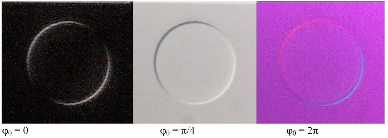
The 3D appearance in DIC arises from directional gradient contrast. DIC converts differences in optical path length between two laterally sheared beams into intensity variations. This produces shadow‑like gradients that mimic shading from a directional light source. However, this is not a measurement of surface height or physical topography. The intensity depends on the gradient of optical path length along the shear direction and on the bias retardation setting. To infer actual height or thickness, you would need a quantitative method designed for phase measurement, not standard DIC.
Final Thoughts on Choosing the Right Optical Contrast for Light Microscopy
Brightfield, darkfield, phase contrast, and DIC are complementary strategies for turning transparent samples into meaningful images. Brightfield is universal and faithful to absorption, particularly with stains. Darkfield isolates scattered light, making edges and tiny particles glow against darkness. Phase contrast systematically translates phase differences to intensity, revealing live, transparent specimens with minimal preparation. DIC elevates gradient contrast with crisp, directional shading, ideal for high‑resolution visualization when polarization‑compatible optics and substrates are used.
The best choice depends on your specimen and goals. For live cells or thin transparent samples, start with phase contrast and consider DIC for halo‑free detail. For tiny particles and sharp edges, darkfield excels. For stained sections, brightfield remains the go‑to. When you switch modes, recalibrate your expectations: each method’s strengths come with characteristic artifacts and interpretation rules. Use internal cross‑checks—view the same field with two methods—to separate genuine features from method‑specific appearances, as discussed in Interpreting Images.
If you found this guide helpful, consider subscribing to our newsletter to receive future articles that continue building a rigorous, practical foundation in microscopy—from illumination strategy and sample mounting to advanced contrast methods and image interpretation. Explore related topics within this series by jumping back to How Optical Contrast Works or comparing feature‑specific guidance in Choosing Between Methods.