
Table of Contents
- What Do Numerical Aperture and Resolution Really Mean?
- Abbe and Rayleigh Criteria: Practical Limits of Detail
- Magnification vs Resolution: Avoiding Empty Magnification
- How Illumination and Contrast Mechanisms Shape What You See
- Condenser Aperture, Illumination NA, and Köhler Principles
- Refractive Index, Immersion Media, and Cover Glass Effects
- Digital Cameras, Pixel Sampling, and the Nyquist Criterion
- Optical Aberrations, Alignment, and Practical Trade-offs
- Real-World Scenarios: Choosing NA, Wavelength, and Contrast
- Frequently Asked Questions
- Final Thoughts on Choosing the Right Numerical Aperture and Illumination
What Do Numerical Aperture and Resolution Really Mean?
Numerical aperture (NA) and resolution are the intertwined pillars of image detail in optical microscopy. If you want sharper images, clearer edges, and more reliable measurements, it helps to start with these two ideas and how they connect to illumination, contrast, and even camera pixels. In short, NA tells you how much light an objective can accept (and under Köhler illumination, how much angle of light your condenser can deliver), while resolution is about how small two features can be and still be distinguished as separate.
Numerical aperture is defined as NA = n · sin(θ), where n is the refractive index of the imaging medium (air, water, oil) and θ is the half-angle of the widest cone of light that can enter the objective. Higher NA means a wider light cone and, consequently, a finer ability to resolve detail. Commonly, air objectives have NA values up to about 0.95, water-immersion objectives often reach around 1.0–1.2, and oil-immersion objectives may be labeled 1.25–1.49. The key takeaway: as NA increases, potential resolution improves, but alignment, coverslip matching, illumination, and sample preparation must support that potential.
Resolution sets the smallest feature size you can reliably separate. It depends on wavelength (λ) and NA. For incoherent widefield imaging, a widely used benchmark is the Rayleigh criterion, which gives a lateral (x–y) distance for just-resolvable points of approximately 0.61 · λ / NA. A shorter wavelength improves resolution; so does a higher NA. But shorter wavelengths can reduce signal, alter sample appearance, or increase photodamage in certain contexts. In white-light brightfield, many practitioners consider green light (~550 nm) a useful reference point for discussing resolution limits.

These principles form the groundwork for the rest of this article. We will connect NA and resolution to practical concerns you face at the bench: avoiding empty magnification, selecting immersion media, setting illumination aperture, and matching camera sampling to the optics. Where it helps, we’ll link to other sections—for instance, the trade-off between NA and contrast is explored in How Illumination and Contrast Mechanisms Shape What You See, and pixel sampling is detailed in Digital Cameras, Pixel Sampling, and the Nyquist Criterion.
Abbe and Rayleigh Criteria: Practical Limits of Detail
You will often encounter two related expressions for the diffraction-limited resolution of an optical microscope. Abbe’s formula describes the smallest resolvable spacing in a periodic structure (such as a grating), while Rayleigh’s criterion is a criterion for separating two incoherent point sources (point-like details). Both are valid within their assumptions and give a consistent message: the limit of detail is set by wavelength and NA.
-
Abbe limit (periodic features):
d ≈ λ / (2 · NA). For a line grating, this formula estimates the smallest resolvable pitch when the objective and illumination are appropriately matched. -
Rayleigh criterion (point sources, lateral resolution):
d ≈ 0.61 · λ / NA. The constant 0.61 derives from the first zero of the Airy diffraction pattern. Two points are said to be just resolved when the principal maximum of one point coincides with the first minimum of the other.
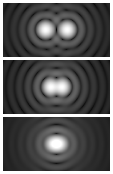
Axial (z) resolution in widefield imaging is poorer than lateral resolution. A common, order-of-magnitude expression is Δz scaling as ≈ 2 · n · λ / NA² for incoherent imaging, where n is the refractive index of the immersion medium. The exact constant depends on the definition used (e.g., full-width at half-maximum of the point-spread function), but the inverse-square dependence on NA and linear dependence on wavelength are robust and intuitive: improve axial sectioning by increasing NA and/or using shorter wavelengths.
These relations do not automatically guarantee that your microscope will reach them. Several factors must be right to approach the diffraction limit:
- Correct coverslip thickness: Many high-NA objectives are designed for 0.17 mm coverslips (#1.5). Deviations can introduce spherical aberration and reduce effective resolution. See Refractive Index, Immersion Media, and Cover Glass Effects for why this matters.
- Appropriate illumination NA: Under Köhler illumination, the condenser aperture controls the illumination cone. Setting it relative to the objective NA affects resolution and contrast. Details are in Condenser Aperture, Illumination NA, and Köhler Principles.
- Optical correction and alignment: Objectives with higher NA are more sensitive to misalignment and aberrations from the rest of the optical train. See Optical Aberrations, Alignment, and Practical Trade-offs.
- Sampling (for digital imaging): Even with perfect optics, the camera must sample fine enough to capture the detail. The Nyquist criterion is discussed in Digital Cameras, Pixel Sampling, and the Nyquist Criterion.
In practice, the Abbe and Rayleigh limits are useful as design targets and reality checks. If your sample contains details much smaller than your theoretical lateral resolution, you will not be able to distinguish them as separate features in a conventional widefield microscope. Instead, consider contrast-enhancement mechanisms (e.g., phase contrast or DIC) to improve visibility of features that are near the resolution limit, understanding that contrast mechanisms can make details easier to discern without changing the diffraction limit itself.
Magnification vs Resolution: Avoiding Empty Magnification
Magnification makes things look bigger; resolution makes distinct features separable. It is possible to “magnify blur”—a phenomenon known as empty magnification—when total magnification outstrips the resolving power of the objective. Empty magnification reduces image brightness and adds no new detail.
A practical rule of thumb for visual observation is to target a total magnification of roughly 500× to 1000× the objective’s NA. For example, an objective with NA 0.65 is well served by about 325× to 650× total magnification. Below this range, you may not be leveraging the objective’s full resolving power. Far above it, you may enlarge the image without revealing additional structure. This rule is heuristic, not a law of physics, but it reflects the relationship between human visual acuity and the diffraction-limited detail in the image projected by the objective.
Total magnification is the product of objective magnification and the intermediate optics (e.g., eyepieces or tube lens/system magnification). But decisions about magnification should not be isolated from NA. Some key points:
- NA governs detail, magnification governs size on the retina or sensor: If you switch from a 40×/0.65 to a 40×/0.85 objective, you have the same nominal magnification but higher NA and better potential resolution.
- Contrast and SNR matter: Even with adequate magnification, low-contrast features can be hard to see. Enhancing contrast through illumination settings or phase/DIC (see illumination and contrast) can be as important as magnification.
- Brightness scales unfavorably with magnification at fixed NA: Increasing magnification spreads the light over a larger image, reducing apparent brightness. Use magnification thoughtfully to balance brightness, contrast, and perceived detail.
- For cameras, sampling replaces eyeballs: The Nyquist criterion will guide the needed magnification/pixel size combination to record the available detail (see digital sampling).
Consider planning from the resolution requirement backward. Ask: What NA and wavelength are needed to resolve the features of interest? Then, choose magnification and camera sampling to faithfully capture that detail without wasting light or image real estate.
How Illumination and Contrast Mechanisms Shape What You See
Illumination does more than brighten the field of view. Its geometry and coherence determine how spatial frequencies in your sample are transmitted to the image. The most widely used scheme for brightfield is Köhler illumination, which decouples image formation from the filament or LED emitter structure and allows control over the illumination numerical aperture via the condenser aperture diaphragm. Changes here strongly affect contrast and resolution.
Intuitively, increasing the illumination NA (by opening the condenser aperture diaphragm) improves the system’s ability to transfer fine detail but reduces image contrast. Decreasing illumination NA increases contrast but attenuates the highest spatial frequencies reaching the objective. This is why practitioners often set the condenser aperture diaphragm to a fraction of the objective NA—commonly around 60–80% of the objective NA in brightfield for a balance of resolution, contrast, and depth of field. This is a guideline, not a fixed rule, and the optimal setting depends on the sample.
Contrast mechanisms build on illumination control to reveal otherwise invisible details:
- Brightfield: Relies on absorption, scattering, and refractive index variations. Best for inherently stained or naturally pigmented specimens and high-contrast edges.
-
Phase contrast: Converts phase shifts (from refractive index differences) into intensity variations. It increases detectability of transparent features without changing the diffraction limit. Keep in mind that halos and shade-off artifacts can appear near edges.

A diagram of a working principle of phase contrast microscopy. — Artist: Egelberg - Differential interference contrast (DIC): Enhances gradients and gives a pseudo-3D relief effect by interfering two sheared beams. It can make subtle topography and phase gradients highly visible. Like phase contrast, DIC enhances contrast but does not bypass diffraction limits.
- Darkfield: Blocks direct (undeviated) light and images only scattered light from the specimen. Excellent for small, high-scattering particles and edges. Requires careful condenser selection and alignment to maintain a dark background.
- Polarization contrast: Useful for birefringent specimens (e.g., crystals, some polymers). Contrast depends on sample orientation and optical anisotropy.
Selecting a contrast method does not change the underlying resolution limit set by NA and wavelength, but it changes the modulation transfer of the system for different spatial frequencies and features. In practice, this can make fine details more discernible, especially when the features have low inherent absorption but produce phase shifts or directional scattering.
Finally, illumination spectrum matters. Shorter wavelengths yield higher theoretical resolution, but they also interact differently with the specimen’s absorption and scattering, and may reduce camera sensitivity or induce higher photobleaching in fluorescence contexts. For white-light brightfield imaging, filtering to a narrower green band can sometimes stabilize contrast and resolution by reducing chromatic blur. These trade-offs are elaborated in Real-World Scenarios: Choosing NA, Wavelength, and Contrast.
Condenser Aperture, Illumination NA, and Köhler Principles
Köhler illumination establishes a conjugate relationship between the field diaphragm and the specimen plane, and between the condenser aperture diaphragm and the objective back focal plane. The result is uniform field illumination and independent control over the illumination cone angle. Conceptually, three adjustable elements matter:
- Field diaphragm: Controls the illuminated area on the specimen and helps reduce stray light and glare when sized just larger than the field of view.
- Condenser aperture diaphragm: Determines the illumination NA—effectively, the angular spread of rays illuminating the sample.
- Condenser focus and centering: Ensure the illumination cone is well formed and symmetric around the optical axis, supporting even resolution and contrast across the field.

Why does the condenser aperture NA matter so much? Because resolution and contrast are two sides of the same coin when it comes to angular illumination. A larger illumination NA feeds higher spatial frequencies into the objective, increasing resolution potential but reducing image contrast and depth of field. A smaller illumination NA does the opposite. A broadly used starting point is to set the condenser aperture to a fraction of the objective NA (e.g., ~0.6–0.8 × objective NA) and adjust based on the sample’s transparency and the features of interest.
Some microscopes provide a direct readout of illumination NA or an iris scale; others may require a calibration or a visual estimate using the back focal plane (BFP) view. When the condenser aperture is well matched to the objective, the BFP of the objective shows the aperture edge crisply, centered, and at the intended diameter. Although the methods to achieve this are instrument-specific, the principle is general: align and size the illumination cone to suit the objective and the sample. For considerations relating to refractive index and immersion, see Refractive Index, Immersion Media, and Cover Glass Effects.
Note that special contrast methods modify the illumination path: phase contrast introduces annuli in the condenser and phase plates in the objective; DIC adds prisms and polarizers; darkfield uses central stops or specialized condensers. In each case, the concept of “illumination NA” still applies, but practical settings are constrained by the contrast optics.
Refractive Index, Immersion Media, and Cover Glass Effects
Because NA = n · sin(θ), the refractive index of the medium between the specimen and the objective front lens directly affects both resolution and light-gathering ability. Air (n ≈ 1.00), water (n ≈ 1.33 at visible wavelengths), and immersion oil (n ≈ 1.515 at standard temperature and spectral lines) are the primary cases in brightfield and contrast microscopy. For a given cone angle, switching to a higher-index immersion medium increases NA and thus improves potential resolution and brightness at high spatial frequencies.
However, achieving this improvement requires that several conditions be satisfied:
- Coverslip thickness matching: Many high-NA objectives are corrected for a specific coverslip thickness, commonly 0.17 mm (#1.5). If the actual coverslip deviates significantly, spherical aberration increases, degrading resolution and contrast. Some objectives provide a correction collar to compensate within a limited range; others are fixed.
- Index matching to the coverslip: Standard immersion oils are formulated to match the refractive index of the coverslip glass to minimize refraction at the interface and preserve high-angle rays. Using oil with the intended index supports the objective’s design performance.
- Sample medium and mounting: If the sample is in an aqueous medium under a glass coverslip but the objective is oil-immersion, there is a stack of refractive indices (oil–glass–water). While objectives are designed to tolerate this, significant deviations (e.g., thick media layers, nonstandard mounting materials) can introduce aberrations. Water-immersion objectives are often preferred for thick aqueous samples to reduce index mismatch.
- Working distance and NA: High-NA objectives usually have short working distances and are more sensitive to small separations or tilt between the coverslip and objective front lens. Mechanical stability and careful handling matter.
What if your sample is uncovered or too thick for a coverslip? Air objectives can be suitable when the required NA is modest and when placing a coverslip would compromise the specimen. For high-NA imaging without a standard coverslip, specialized objectives exist, but the general principle remains: index mismatches and layer thicknesses influence aberrations and the effective NA at the specimen.
A related consideration is wavelength dependence of refractive index (dispersion). Multi-color imaging can reveal slight focus shifts between colors due to chromatic aberration in the optics and dispersion in immersion media. Achromat, fluorite (semi-apochromat), and apochromat objectives differ in how well they correct for chromatic and spherical aberrations across wavelengths. These corrections don’t alter the diffraction limit but improve how close you can get to it simultaneously across multiple colors.
Digital Cameras, Pixel Sampling, and the Nyquist Criterion
In digital imaging, resolution also has a sampling requirement: to capture fine detail reliably, the camera’s effective pixel size at the specimen plane must be small enough relative to the diffraction-limited feature size. The Nyquist–Shannon sampling theorem provides the guide: sample at least twice per smallest resolvable period to avoid aliasing and preserve information.
For incoherent widefield imaging using a conventional approximation of lateral resolution r ≈ 0.61·λ/NA, a widely used practical target for sampling is an effective pixel size at the specimen of roughly ≤ r/2 (and often closer to r/2–r/3 to accommodate system MTF roll-off). Translating this into camera and optics parameters:
- Effective pixel size at specimen = (camera pixel size) / (total magnification from specimen to sensor). For finite-conjugate microscope cameras, total magnification is governed by objective magnification, tube lens, relay optics, and any intermediate magnifiers.
- Sampling target: Choose magnification so that the effective pixel size is approximately ≤ (0.61·λ/NA) / 2. For example, with λ = 550 nm and NA = 0.75, r ≈ 0.61×550/0.75 ≈ 447 nm; r/2 ≈ 224 nm. If your camera pixel is 3.45 µm, you’d aim for a total magnification of about 3.45 µm / 0.224 µm ≈ 15.4× between specimen and sensor.
- Oversampling vs undersampling: Oversampling (much smaller effective pixel size than r/2) captures no new optical detail but reduces per-pixel signal and frame rate for a given exposure. Undersampling (pixel size larger than r/2) risks aliasing and loss of small features. A modest degree of oversampling is often acceptable to accommodate variations in wavelength and NA across objectives.
Rolling-shutter, read noise, and bit depth belong to the broader signal-to-noise story, but they do not modify the fundamental optical-sampling requirement. If your optics cannot resolve a feature, no pixel density will recover it. Conversely, even the best optical resolution is of limited value without adequate sampling and contrast. For a complementary discussion on balancing contrast and illumination NA, see Condenser Aperture, Illumination NA, and Köhler Principles.
When multiple objectives are used, consider whether the camera field of view and sampling remain appropriate across magnifications. Some systems use relay lenses or change camera sensors to maintain similar sampling strategies across objectives. The aim is consistent: ensure effective pixel size remains in a range that supports the highest spatial frequency content you expect to record.
Optical Aberrations, Alignment, and Practical Trade-offs
Reaching diffraction-limited performance requires more than theory; it depends on optical aberrations and alignment throughout the microscope. High-NA objectives are engineered to correct a suite of aberrations, but the system can still suffer from residuals introduced by components upstream and downstream of the objective.
Common aberrations and issues include:
- Spherical aberration: Rays farther from the optical axis focus at different axial positions than paraxial rays. Caused by mismatched coverslip thickness, refractive index deviations, or incorrect correction collar settings. Symptoms include reduced contrast and softened detail, especially at high NA.
- Chromatic aberration: Different wavelengths focus at different axial positions (longitudinal chromatic) or form images of different magnification (lateral chromatic). Objective design (achromat, fluorite, apochromat) dictates the degree of correction. Using narrowband illumination can reduce chromatic blur in brightfield.
- Astigmatism and coma: Off-axis aberrations that distort points into lines or comet-like shapes, especially toward the field edges. They can arise from misalignment, tilted coverslips, or component tolerances.
- Field curvature and distortion: The focal plane may be curved, and magnification may vary across the field. Some objectives or tube lenses are designed to flatten the field for imaging sensors.
- Mechanical stability and tilt: Even small tilts or vibrations can degrade high-NA performance. Good mounting and level specimen support help preserve resolution.
Alignment connects directly to Köhler illumination and the condenser. If the illumination cone is decentered or asymmetric, resolution and contrast vary across the field. For phase contrast and DIC, alignment of annuli, prisms, and polarizers is especially important. While instrument-specific alignment procedures vary, recognizing the symptoms—uneven illumination, shifting halos, directional blur—is a step toward diagnosing issues without engaging in trial-and-error.
There are also fundamental trade-offs:
- NA vs depth of field: Higher NA yields better lateral and axial resolution but a shallower depth of field. If your sample has appreciable thickness, you may need to choose between resolving the highest detail in one plane and maintaining acceptable focus across depth.
- Resolution vs contrast: Opening the condenser aperture increases resolution but can reduce contrast. Closing it improves contrast but can attenuate fine detail. The optimal balance depends on sample transparency and the spatial frequencies of interest. See How Illumination and Contrast Mechanisms Shape What You See.
- Shorter wavelength vs specimen impact: Blue light improves theoretical resolution compared with green, but it may reduce signal for some detectors or alter specimen appearance due to different absorption/scattering at shorter wavelengths.
In many practical settings, you will not drive every parameter to its theoretical optimum. Instead, you will choose settings that maximize the information you need while preserving signal-to-noise and making the image interpretable. The “best” image is the one that answers your question reliably, not necessarily the one that uses the largest NA or shortest wavelength on the spec sheet.
Real-World Scenarios: Choosing NA, Wavelength, and Contrast
Let’s synthesize the physics into concrete scenarios. While every sample is different, these examples illustrate the reasoning process behind selecting NA, illumination, and contrast mechanisms. Where relevant, we will cross-link to deeper explanations in other sections like Magnification vs Resolution and Digital Cameras, Pixel Sampling, and the Nyquist Criterion.
Scenario 1: High-contrast stained sections
Suppose you are viewing thin, stained tissue sections in brightfield. Stains provide strong absorption contrast, allowing the condenser aperture to be opened relatively wide without making the image look flat. You can exploit higher illumination NA to capture fine detail and approach the objective’s resolution limit. With an objective near NA 0.75 and green illumination, you might aim for a condenser aperture set to roughly 70–80% of the objective NA for a strong balance of contrast and resolution.
- Benefit: Strong inherent contrast supports higher illumination NA and fine detail.
- Consideration: If the image looks flat, slightly reduce the condenser aperture to regain mid-frequency contrast.
- Sampling: Ensure the camera’s effective pixel size is around r/2 or a bit smaller (see Nyquist).
Scenario 2: Transparent, live aqueous specimens (e.g., pond water)
Transparent features have low absorption; they primarily alter the phase of transmitted light. In brightfield, contrast may be weak unless you reduce illumination NA. Alternatively, phase contrast or DIC can dramatically improve visibility. If using brightfield alone, slightly stopping down the condenser can improve contrast, but this comes at the expense of some high-frequency detail.

- Benefit: Phase or DIC enhances detectability of transparent edges and structures without changing the diffraction limit.
- Consideration: For thicker water samples, water-immersion objectives reduce index mismatch and spherical aberration compared with oil-immersion designs (see immersion effects).
- Sampling: Motion can blur high frequencies; to preserve detail, ensure short exposure times and adequate illumination.
Scenario 3: Fine particle edges with darkfield
When imaging small particles or edges that scatter light strongly, darkfield can produce striking contrast against a black background. The darkfield condenser blocks the central illumination so that only scattered light enters the objective. Because the image relies on scattering, very high NA objectives may not be necessary to achieve visually compelling contrast, but higher NA can still improve edge sharpness and capture finer scattering angles.
- Benefit: Excellent contrast for small, scattering features; easy visual detection.
- Consideration: Background brightness increases if alignment is off or if the sample scatters light into the blocked region.
- Sampling: Adjust exposure to avoid saturating bright scatterers while still recording dim features.
Scenario 4: Large, thick specimens with limited flatness
For thick, uneven specimens, pushing NA to the maximum can yield razor-thin depth of field, making interpretation difficult. Slightly reducing NA (choosing a lower-NA objective or lowering illumination NA) can increase depth of field and overall image interpretability, even though the theoretical resolution is lower.
- Benefit: Improved depth of field eases navigation and qualitative assessment of structures.
- Consideration: If specific fine features are critical, consider acquiring multiple focal planes and integrating them computationally (focus stacking), if appropriate for your application and specimen stability.
- Sampling: Lower NA relaxes sampling requirements but keep pixel size small enough to avoid aliasing at the reduced resolution limit.
Scenario 5: Multi-wavelength brightfield
Changing filters in brightfield can alter both contrast and resolution. Shorter wavelengths improve resolution but can change the relative contrast of different structures due to wavelength-dependent absorption and scattering. If you need consistent edge sharpness, standardizing on a green bandpass filter can provide a compromise between resolution and signal.
- Benefit: Green light often provides a stable reference for resolution and focusing.
- Consideration: If chromatic aberration is visible as color fringing at edges, try a narrower spectral band or an objective with better chromatic correction.
- Sampling: Changing wavelength changes r; verify your sampling remains at or above Nyquist when switching colors (see Nyquist).
Scenario 6: Measuring feature sizes quantitatively
If your goal is to measure distances near the resolution limit, you benefit from higher NA and stable, high-contrast imaging. Ensure that the illumination NA is sufficiently open to transmit high spatial frequencies and that aberrations are minimized. Calibrate the pixel size at the specimen using a stage micrometer and the exact optical configuration; then apply consistent contrast settings to avoid biasing edge detection.
- Benefit: Quantitative reliability rises when optics, illumination, and sampling match the detail scale of interest.
- Consideration: Edges near the diffraction limit are inherently blurred by the point-spread function; reported widths depend on thresholding. Use consistent methods.
- Sampling: Aim for at least r/2 effective pixel size; modest oversampling can aid sub-pixel interpolation in fitting routines, with the trade-off of lower per-pixel SNR.
Scenario 7: Switching between air and oil objectives
Air objectives are convenient and sufficient for many tasks, but at high magnifications the jump to oil-immersion can yield a notable gain in resolution and brightness due to higher NA. If your sample is under a standard coverslip and you need to resolve fine features, oil can be worthwhile. Pay attention to cleanliness and to using oil compatible with the objective’s specifications.
- Benefit: Higher NA and better high-frequency transmission.
- Consideration: If the sample is thick and aqueous, consider water-immersion objectives to reduce mismatch across the coverslip-water interface (see immersion).
- Sampling: Verify that camera sampling still meets Nyquist for the increased NA; you may need more total magnification to keep effective pixel size small enough (see sampling).
Frequently Asked Questions
Does a higher NA always produce a better image?
Higher NA improves theoretical resolution and can increase brightness at high spatial frequencies. However, it also reduces depth of field and is more sensitive to aberrations, alignment, and coverslip mismatch. If the sample is thick, weakly scattering, or difficult to align, the benefits of very high NA can be offset by practical constraints. The “best” image balances NA with contrast, specimen thickness, and the question being asked. If you need a refresher on the trade-offs, see Optical Aberrations, Alignment, and Practical Trade-offs and Illumination and Contrast.
What’s the difference between Abbe’s limit and the Rayleigh criterion?
Abbe’s limit describes the smallest resolvable period of a periodic structure under coherent or partially coherent illumination and is often written as d ≈ λ/(2·NA). The Rayleigh criterion concerns the separation of two incoherent point sources and is commonly expressed as d ≈ 0.61·λ/NA. They are complementary views of the same diffraction physics and give similar scales for resolution. The constants differ because they refer to different measurement contexts (gratings versus point separation) and definitions of “just resolved.” Both emphasize the same levers: shorter wavelengths and higher NA improve resolution. For more context, visit Abbe and Rayleigh Criteria.
Final Thoughts on Choosing the Right Numerical Aperture and Illumination
The sharpest, most informative microscope images arise when optics, illumination, contrast, and sampling work together. Numerical aperture sits at the center: it determines how much fine detail can pass through the system, in concert with wavelength. But the surrounding choices—condenser aperture, contrast mechanism, immersion medium, coverslip thickness, and camera sampling—decide whether you actually see that detail and whether it’s captured reliably on a sensor or perceived clearly by the eye.

If you remember only a few points, make them these:
- Resolution scales favorably with NA and shorter wavelengths; lateral resolution is often approximated by 0.61·λ/NA in widefield imaging.
- Match illumination NA to the objective and sample: open for resolution, close for contrast, and aim for a balanced fraction of the objective NA in brightfield.
- Use immersion and coverslips as designed for high-NA objectives; mismatches introduce spherical aberration and reduce effective resolution.
- Avoid empty magnification; for visual work, stay near 500–1000× NA. For cameras, ensure Nyquist sampling at about r/2 effective pixel size.
- Choose contrast methods (brightfield, phase, DIC, darkfield, polarization) to enhance detectability without expecting them to exceed diffraction limits.
If this deep dive clarified how NA, resolution, and contrast interlock, explore our related fundamentals and accessory guides for more physics-backed insights. Consider subscribing to our newsletter to get future articles on microscope fundamentals, accessories, and applications delivered straight to your inbox.


