
Table of Contents
- What Is Numerical Aperture in Optical Microscopy?
- Resolution, Diffraction Limits, and Why NA Matters
- Magnification vs. Resolution: Avoiding Empty Magnification
- Illumination, Condenser NA, and Köhler Illumination Basics
- Wavelength Choice and Image Contrast Mechanisms
- Immersion Media, Refractive Index, and Spherical Aberration
- Depth of Field, Working Distance, and Field of View
- Digital Imaging, Pixel Size, and Nyquist Sampling
- Common Optical Aberrations and Objective Corrections
- Practical Trade-offs and a Quick Selection Checklist
- Frequently Asked Questions
- Final Thoughts on Choosing the Right NA and Magnification
What Is Numerical Aperture in Optical Microscopy?
Numerical aperture (NA) is the single most important number printed on a microscope objective. It encapsulates how much light the objective can gather from the specimen and, critically, how much angular range of diffracted light it can accept. In practical terms, a higher NA supports better lateral resolution, improved brightness (for a given illumination), and thinner depth of field. NA is a property of both objectives and condensers, and it directly governs the resolving power of a transmitted or reflected light microscope.
The formal definition is concise:
NA = n · sin(θ)
Attribution: QuodScripsiScripsi
where n is the refractive index of the medium between the front of the objective and the specimen (air, water, glycerol, or immersion oil) and θ is the half-angle of the widest cone of light that can enter (for objectives) or illuminate (for condensers) the specimen. In air, n ≈ 1.0, so objectives working in air are geometrically limited: they cannot exceed an NA of about 1.0 because sin(θ) ≤ 1. By using immersion media with n > 1.0, such as oil with n ≈ 1.515, an objective can achieve NA values above 1.0, enabling significantly finer detail to be resolved.
NA, illumination, and sample optics are interconnected. The condenser’s NA controls the range of incident angles that illuminate the specimen. For conventional brightfield imaging, achieving the objective’s full resolving potential typically requires the condenser NA to be comparable to, or not substantially lower than, the objective NA. When the condenser NA is set much smaller, high-angle diffracted information is not sufficiently illuminated or transmitted, and the effective resolution is reduced.
It is common to treat NA as the objective’s “resolution number,” but that perspective is incomplete without considering the illumination geometry and the wavelength of light used. NA also influences image brightness: for a given exposure and transmission, image irradiance at the camera or eye scales approximately with the square of NA in many imaging configurations, because larger apertures transmit more light-cone solid angle. This is one reason high-NA objectives can appear brighter when matched with proper condenser settings and well-aligned illumination.
Objective NA versus Condenser NA
The objective and condenser form a complementary pair in transmitted light microscopy. A heuristic rule for brightfield is that to achieve the best resolution the product of the optical train should not be bottlenecked by an undersized condenser aperture. In other words, even if the objective has high NA, a small condenser NA restricts the angular spectrum of illumination and underutilizes the objective’s capability. While the exact influence depends on coherence and contrast modality, it is generally correct that matching objective NA with condenser NA enables you to reach the theoretical limits discussed in Resolution, Diffraction Limits, and Why NA Matters.
Immersion Objectives and NA Greater Than 1.0
Oil-immersion and other immersion objectives exploit media with n > 1 to gather steeper diffraction angles, raising NA and, correspondingly, practical resolving power. Because NA = n · sin(θ), if the medium’s refractive index increases while the geometry of the front lens remains similar, NA increases proportionally. However, immersion requires careful attention to refractive index matching and coverslip specifications to minimize aberrations that can negate the theoretical gains of higher NA.
Resolution, Diffraction Limits, and Why NA Matters
Resolution answers the question, “How close can two details be and still be distinguished as separate?” It is not the same as magnification. Resolution depends on the wave nature of light and the way lenses collect diffracted orders from fine features. A perfect lens cannot image arbitrarily small details with visible light because the diffraction of light sets a fundamental limit governed by NA and wavelength.
Two closely related formulations are widely cited in optical microscopy:
- Rayleigh criterion (widefield, incoherent imaging):
d ≈ 0.61 · λ / NA - Abbe limit (spatial frequency perspective):
d ≈ λ / (2 · NA)
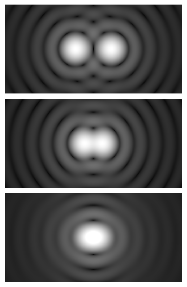
This image uses a nonlinear color scale (specifically, the fourth root) in order to better show the minima and maxima.
Attribution: Spencer Bliven
These expressions differ slightly in their constants and the assumptions about the imaging system and coherence, but they agree on the essential scaling: resolution improves (i.e., d decreases) as NA increases and as the illumination/emission wavelength λ decreases. For typical visible wavelengths, modest changes in λ are often less impactful than doubling NA. This makes NA the dominant parameter in conventional brightfield and epi-illumination microscopy.
Key intuition: doubling NA roughly halves the theoretical lateral resolution limit (for the same wavelength and imaging conditions). No amount of extra magnification can recover details lost to insufficient NA.
Lateral vs. Axial Resolution
Lateral resolution refers to detail in the plane of the specimen (x–y). Axial resolution refers to separability along the optical axis (z), which is important for thick or three-dimensional specimens. For widefield microscopy, a widely used approximation for axial resolution (full width at half maximum of the point spread function) is:
Δz ≈ 2 · n · λ / NA²where n is the refractive index of the imaging medium. This relationship highlights that axial resolution improves strongly with increasing NA (quadratic dependence), and with shorter wavelengths. A consequence is that high-NA oil-immersion objectives not only improve lateral resolution but also thin the optical section, enhancing contrast for features at a focal plane—provided the illumination and sample are suitable.
Cutoff Spatial Frequency and Information Throughput
Another way to think about resolution uses spatial frequencies. For incoherent imaging (typical brightfield and epifluorescence detection of emitted light), the optical transfer function (OTF) has a cutoff spatial frequency approximately:
f_c ≈ 2 · NA / λThis is the highest spatial frequency (finest detail per unit length) that can be transferred by the optical system. As features approach the cutoff, contrast diminishes. The modulation transfer function (MTF), which is the magnitude of the OTF, decays continuously with frequency and reaches zero at the cutoff. High-quality imaging requires that the objective (and condenser, when relevant) support these frequencies and that the camera sampling be adequate to record them without aliasing.
In coherent imaging (e.g., certain laser-based or interference setups), relationships differ, and the cutoff frequency depends linearly on NA rather than twice NA. For broad, practical microscopy discussions targeted at students and hobbyists, treating standard brightfield/epifluorescence as incoherent or partially coherent is a useful approximation, which is why the 0.61 · λ / NA expression remains so prevalent.
Magnification vs. Resolution: Avoiding Empty Magnification
Magnification tells you how big things look (on the sensor or to your eye). Resolution tells you how much new detail becomes visible. An optical system that magnifies without increasing resolvable detail merely spreads the same information over a larger area—this is empty magnification.
For visual observation with eyepieces, a time-tested heuristic is that useful total magnification is roughly on the order of 500–1000× the objective’s NA. For example, an objective with NA 0.65 might support total magnifications in the range of a few hundred to around 650×, sometimes up to ~650–650 NA times 1000 (?)—but remember, this is a rule of thumb, not a hard limit. The point is that if you far exceed this range, the image may look larger but not convey additional resolvable structure. When imaging with cameras, the analogous concept is proper sampling of the point spread function: magnification should be chosen so that the camera’s pixels sufficiently sample the smallest details your optics can resolve.
Objective Magnification, Tube Lenses, and Eyepieces
In finite-conjugate microscopes (less common in modern systems), the objective’s nominal magnification and the eyepiece magnification multiply to give total magnification at the eye. In infinity-corrected microscopes, the objective projects collimated light that is focused by a tube lens; the objective’s magnification is defined by the ratio of tube lens focal length to objective focal length. For visual use, the eyepiece provides an angular magnification to your eye. While these details matter for system design, the practical guidance remains: do not push magnification much beyond what your NA and wavelength can resolve.
Choosing Magnification for Cameras
For digital imaging, “total magnification” is less helpful than effective pixel size at the specimen plane. To record all resolvable detail, you should sample the image at or above the Nyquist rate for the highest spatial frequency your optics can transfer. A practical way to evaluate this is to compute how a camera’s pixel size, after division by total optical magnification to the sensor, compares with the expected lateral resolution d from Rayleigh’s criterion. As a rule of thumb, aim for approximately 2–3 pixels across the smallest resolvable feature, or said differently, an effective specimen-plane pixel size in the range of about 0.33–0.5 times the system’s lateral resolution limit. This ensures that magnification is used efficiently to capture actual information rather than merely scaling the image.
When your magnification is too low for the pixel size, fine detail near the resolution limit becomes under-sampled and may alias, misrepresenting structure. When magnification is too high, the camera records redundant pixels across the same blurred spot, wasting light and disk space without revealing more detail. The sweet spot aligns sampling with optics, as detailed in Digital Imaging, Pixel Size, and Nyquist Sampling.
Illumination, Condenser NA, and Köhler Illumination Basics
Illumination quality and geometry are as important as the objective. In transmitted light microscopy, the condenser forms an aperture that determines the angular distribution of illumination at the specimen. Properly matching the condenser NA to the objective NA and aligning the optical train for even, angle-controlled lighting unlocks the objective’s inherent contrast and resolution.
Condenser NA and Aperture Diaphragm
Most condensers include an aperture diaphragm that sets their effective NA. Opening the diaphragm increases condenser NA, allowing higher-angle rays that can carry finer spatial frequencies. Closing it reduces NA, which can increase depth of field and contrast for some samples but limits the highest resolvable detail. For brightfield imaging of fine structure, the condenser aperture is often set to be comparable to the objective NA. For thicker, low-contrast, or scattering specimens, a somewhat smaller condenser NA may improve visual contrast at the expense of resolution.
The practical trade-off is straightforward:
- Higher condenser NA: better resolution potential, more even illumination of high spatial frequencies, potentially lower image contrast for low-phase objects without additional contrast methods.
- Lower condenser NA: reduced maximum resolution, potentially higher apparent contrast and greater depth of field.
Because the condenser and objective work together, if you are chasing the highest resolution in brightfield, ensure that the condenser NA is not significantly below the objective NA. This point complements the NA definitions in What Is Numerical Aperture in Optical Microscopy?.
Köhler Illumination: Even Field, Controlled Angles
Köhler illumination is the standard approach for obtaining spatially uniform illumination and well-controlled illumination angles at the specimen plane. In Köhler, the field diaphragm is imaged onto the specimen plane through the condenser, while the lamp filament (or LED source) is imaged onto the condenser aperture. The result is even illumination across the field and independent control of the illuminated area (field diaphragm) and the illumination NA (aperture diaphragm). Although the specific alignment steps are not the focus here, understanding Köhler conceptually helps explain why adjusting the field diaphragm affects the illuminated area and adjusting the condenser aperture affects resolution and contrast through NA.

Images donated as part of a GLAM collaboration with Carl Zeiss Microscopy – please contact Andy Mabbett for details.
Attribution: ZEISS Microscopy
In epi-illumination (reflected light microscopy), related principles apply: the illumination pupil is in a plane conjugate to the objective’s pupil, and the numerical aperture of illumination plays a similar role in determining resolution and contrast in reflective or fluorescent imaging modes.
Wavelength Choice and Image Contrast Mechanisms
Wavelength affects both resolution and the way samples interact with light. Shorter wavelengths scatter and diffract more strongly and support higher theoretical resolution (smaller d) for a given NA. However, different specimens have varying absorption and scattering properties as a function of wavelength. In brightfield, if you switch to a shorter-wavelength filter, you may increase resolution slightly but also alter contrast and brightness. In epifluorescence, excitation and emission wavelengths are determined by fluorophore properties, and the detection NA and emission wavelength together determine the achievable resolution in the final image.
Brightfield and Phase Objects
Many biological and transparent specimens are primarily phase objects, meaning they change the phase of light rather than strongly absorbing it. In plain brightfield, these samples can appear low-contrast even if fine structures are present. Contrast mechanisms such as phase contrast and differential interference contrast (DIC) transform phase variations into intensity differences, revealing fine detail that brightfield may hide. While these methods do not change the fundamental diffraction limit (set by NA and wavelength), they make details visible that would otherwise be lost in low-contrast backgrounds.
Partial Coherence and Resolution
Partial coherence—intermediate between fully coherent laser illumination and fully incoherent illumination—affects how illumination NA and objective NA combine to set resolution and contrast. The practical upshot is that optimizing illumination (e.g., using Köhler with an appropriate condenser aperture) is a powerful lever. For most educational and routine imaging in brightfield, treating the system as effectively incoherent is acceptable, which is why the 0.61 · λ / NA rule remains broadly applicable. For specialized interference or coherent techniques, resolution formulas change, and analysis should reflect those specific imaging conditions.
Immersion Media, Refractive Index, and Spherical Aberration
When the space between your specimen and objective is filled with a medium whose refractive index matches the design of the objective, the optical system can accept higher-angle rays with reduced refraction at interfaces. Oil-immersion objectives are designed to use immersion oil with refractive index close to that of glass. Water-immersion and glycerol-immersion objectives use their respective media to lessen index mismatches when imaging aqueous samples or thicker media.
Why Refractive Index Matching Matters
Every interface between materials of different refractive indices bends light according to Snell’s law. If your specimen lies under a standard coverslip and you use an air objective, high-angle rays emerging from the specimen refract at the glass–air interface, potentially falling outside the objective’s acceptance cone. Immersion oil bridges the interface, allowing those high-angle rays to propagate into the objective with minimal bending. This increases effective NA and preserves contrast at high spatial frequencies. It is one reason oil-immersion objectives can reach NA values significantly above 1.0.

Attribution: Thebiologyprimer
Coverslip Thickness and Spherical Aberration
High-NA objectives are designed for a specific coverslip thickness, commonly around 0.17 mm (often labeled as No. 1.5). Deviations from the design thickness or refractive index lead to spherical aberration, which spreads the point spread function, reducing contrast and resolution. Even if an objective’s NA is high, spherical aberration can degrade performance so that the practical resolution is worse than a lower-NA objective with proper correction.
Certain objectives include correction collars that allow limited adjustment to compensate for coverslip thickness variation or refractive index mismatch. These collars shift internal lens group spacing to reduce spherical aberration. They are especially useful for high-NA objectives imaging through non-standard coverslips or mounting media. However, correction collars have limited ranges and are not a substitute for gross mismatches in thickness or index.
Oil vs. Water vs. Glycerol Immersion
Each immersion medium has distinct advantages:
- Oil immersion: highest practical NA among common media, strong correction for imaging through glass coverslips, excellent for thin specimens near the coverslip.
- Water immersion: index closer to aqueous samples; useful for thicker or more hydrated specimens, can reduce spherical aberration when imaging deeper into water-based media relative to oil.
- Glycerol immersion: intermediate refractive index; sometimes beneficial for imaging into media whose index lies between glass and water, reducing refractive index mismatch over depth.
Choice of immersion medium should consider your sample’s environment and imaging depth. Using a medium mismatched to the specimen and coverslip may counteract NA benefits by introducing aberrations. For the highest fidelity, pair immersion media with objectives designed for that medium and ensure the coverslip thickness matches the objective specification, as discussed earlier in this immersion section.
Depth of Field, Working Distance, and Field of View
Depth of field (DOF) measures the thickness of the axial region that appears acceptably sharp around the focal plane. Working distance (WD) is the physical clearance from the objective’s front lens to the specimen at focus. Field of view (FOV) denotes the visible or imaged area in the specimen plane. These practical attributes shape how you can use an objective and are tightly linked to NA and magnification.
How NA Affects DOF
As NA increases, DOF decreases approximately with the square of NA in widefield imaging. A commonly cited approximate relationship for axial resolution, Δz ≈ 2 · n · λ / NA², parallels the notion that high-NA optics resolve thinner axial slices. This is a strength for isolating a focal plane in thin specimens but can make focusing more demanding and may reduce tolerance to sample tilt or surface unevenness.
Shorter wavelengths also reduce DOF. Consequently, imaging with blue light (shorter λ) and high NA produces crisp, thin optical sections, while imaging with longer wavelengths and smaller NA provides greater axial tolerance. Neither is universally better—the choice depends on your specimen and the structures of interest.
Working Distance Trade-offs
High-NA objectives often have shorter working distances because large front lenses and steep light cones must be close to the specimen to capture high-angle rays. This can complicate imaging thick samples or those requiring clearance for manipulation. Long-working-distance (LWD) objectives exist to provide additional clearance, but they typically do so by adopting lower NA or different optical designs that may trade some resolution or brightness.
Field of View and Field Number
Field of view at the specimen is constrained by both the objective magnification and the diameter of the intermediate image that the system can deliver. In visual observation with eyepieces, the field number (FN) is the diameter, in millimeters, of the image that the eyepiece presents. A simple approximation for the diameter of the field of view in the specimen plane is:
FOV_diameter ≈ FN / M_objectiveFor digital imaging, the camera sensor size (and any intermediate relay optics) determines the imaged field. If you increase magnification to satisfy sampling requirements, you will narrow the field unless you also increase sensor size. Balancing resolution needs against the total area you need to observe is a practical, specimen-driven decision.
Digital Imaging, Pixel Size, and Nyquist Sampling
Modern microscopy frequently ends not at the eye but at a camera sensor. In this context, magnification is meaningful only insofar as it maps specimen detail onto camera pixels. Sampling theory provides a rigorous framework: to capture a band-limited signal without aliasing, sample at least twice the highest spatial frequency present. Applying this to optics, the highest spatial frequency supported by the imaging system (for incoherent imaging) is approximately f_c ≈ 2 · NA / λ. The corresponding smallest resolvable feature size (period) is roughly 1 / f_c, and the Rayleigh-based resolution d is within the same scale. The Nyquist condition for the specimen-plane sampling interval p′ is then:
p′ ≤ 1 / (2 · f_c) ≈ λ / (4 · NA)or, when using the Rayleigh formulation for d, a practical rule of thumb is
p′ ≈ d / 2 to d / 3meaning 2–3 pixels across the smallest resolvable feature. Translating this to camera pixels requires knowing the total magnification to the sensor. If a camera has pixel size p at the sensor, and the primary magnification from the specimen to the sensor is M, then the specimen-plane pixel size is p′ = p / M. Adjust magnification (via objective choice and any intermediate optics) to meet the sampling criterion.
Airy Disk at the Image Plane
An alternative, equivalent approach considers the size of the Airy pattern in the image plane. The first dark ring (diameter) at the sensor is about:
Airy_diameter_image ≈ 2.44 · λ · M / NA
Attribution: Anaqreon
Matching pixels to this pattern, a practical guideline is to sample with ~2–3 pixels across the Airy radius, or ~4–6 pixels across the diameter. You do not need to memorize both methods; they are different perspectives on aligning sampling to optical resolution. What matters is consistency: use magnification to ensure that the effective specimen-plane pixel size properly samples the resolution limit set by NA and wavelength.
Signal-to-Noise and Exposure Considerations
Sampling more finely (higher magnification onto the same pixels) spreads photon flux over more pixels, potentially reducing signal-to-noise ratio (SNR) per pixel for a fixed exposure and illumination. Conversely, sampling too coarsely risks aliasing fine features. A balanced choice ensures Nyquist sampling while preserving adequate SNR for the features of interest. This balance is especially important in low-light methods such as epi-fluorescence, where photon budgets are limited.
Common Optical Aberrations and Objective Corrections
Real optical systems deviate from the ideal wavefront because of lens shapes, glass properties, and practical design constraints. These deviations, known as aberrations, reduce image quality even if NA and wavelength suggest high resolution. Objective designs incorporate specific corrections for these aberrations, and manufacturers label objectives to indicate their correction class and intended use. Although we will avoid brand-specific nomenclature, the general families and effects are universal.
Primary Aberrations in Microscopy
- Spherical aberration: Rays passing through the periphery of a lens focus at different axial positions than paraxial rays. In microscopy, it broadens the point spread function and lowers contrast, especially prominent with coverslip mismatch, as highlighted in Immersion Media, Refractive Index, and Spherical Aberration.
- Chromatic aberration: Different wavelengths focus at different axial positions (axial chromatic) or different lateral magnifications (lateral chromatic). High-quality objectives minimize these effects across specified wavelength bands.
- Coma and astigmatism: Off-axis aberrations that distort point images into asymmetric shapes or lines, reducing clarity away from the field center.
- Field curvature and distortion: The focus plane may curve, and magnification may vary across the field, affecting flat-field imaging.
Objective Correction Classes
Common correction families (conceptually) include achromats, fluorites (semi-apochromats), and apochromats, with increasing chromatic correction and typically improved spherical correction as you move up the ladder. Plan-corrected variants flatten the field so edges focus at the same plane as the center. Higher correction levels usually improve image fidelity, particularly at higher NA and over broader wavelength ranges, but may trade cost, weight, or working distance.
Even a well-corrected objective can underperform if other system elements are mismatched. For example, misadjusted condenser aperture, incorrect coverslip thickness, or off-design immersion medium index can introduce aberrations or reduce resolution. Optimal performance arises from coordinated attention to NA, illumination, refractive index, and sampling.
Practical Trade-offs and a Quick Selection Checklist
Choosing the “right” objective, illumination settings, and magnification always involves trade-offs. There is no universal best configuration—only the best for your sample, wavelength regime, and imaging goals. The following list integrates the key principles established throughout this article.
Trade-offs at a Glance
- NA vs. depth of field: Higher NA improves resolution but thins DOF and may shorten working distance.
- NA vs. brightness: Higher NA can deliver higher irradiance to the detector for a given exposure and transmission, but may demand higher-quality alignment and matching condenser NA.
- Condenser aperture vs. contrast: Opening the condenser increases resolution potential; closing it may raise apparent contrast and DOF but sacrifices high-frequency detail.
- Wavelength vs. resolution: Shorter wavelengths improve resolution; longer wavelengths can increase DOF and may be gentler for certain specimens in terms of scattering and contrast.
- Sampling vs. SNR: Finer sampling captures more detail but spreads signal over more pixels; coarser sampling boosts per-pixel SNR but risks aliasing.
- Immersion medium vs. practicality: Oil yields highest NA through glass coverslips; water/glycerol can reduce mismatch for aqueous or thick samples but may limit maximum NA.
Quick Selection Checklist
- Define the smallest feature you care to resolve. Estimate required NA using Rayleigh/Abbe relations with your intended wavelength.
- Choose an objective with NA at or above that requirement. Consider correction class (achromat vs. apochromat) based on your needed fidelity across wavelengths.
- Select an immersion medium compatible with the objective and specimen environment. Verify coverslip thickness specifications to control spherical aberration.
- Plan illumination. Use Köhler principles and set the condenser aperture to support your target resolution. Adjust carefully if you need more contrast at the expense of resolution.
- Match magnification to sampling. Compute specimen-plane pixel size and ensure it meets the Nyquist sampling criterion for your optical cutoff frequency.
- Verify working distance and FOV. Confirm you have enough clearance and that the imaged field suits your task. If you need more area, consider stitching or a lower magnification/NA objective with appropriate sampling trade-offs.
- Validate with a test target. Use a known-resolution specimen or a micrometer scale to confirm that your observed resolution and sampling meet expectations.
Frequently Asked Questions
Does increasing magnification always improve resolution?
No. Resolution is fundamentally limited by NA and wavelength via relations such as d ≈ 0.61 · λ / NA. Beyond a certain point, increasing magnification simply enlarges the same diffraction-blurred details—this is empty magnification. Choose magnification so that the camera or eye samples the resolvable detail adequately, as described in Digital Imaging, Pixel Size, and Nyquist Sampling.
How should I set the condenser aperture for best results?
For brightfield, start by matching the condenser NA to be comparable to the objective NA to support the objective’s full resolving capability. If the specimen is low-contrast or thick, slightly closing the condenser aperture can improve apparent contrast and increase depth of field, at the cost of reducing the highest resolvable spatial frequencies. The optimal setting depends on your sample and imaging goals; revisit Illumination, Condenser NA, and Köhler Illumination Basics to understand the trade-off.
Final Thoughts on Choosing the Right NA and Magnification

Attribution: Ernst Leitz (Firm)
Numerical aperture, resolution, and magnification are intertwined pillars of optical microscopy. NA—shaped by objective design, immersion medium, and condenser settings—sets the stage for how much detail you can see. Wavelength modulates this limit, tilting the balance toward finer or thicker sections. Magnification, meanwhile, is the messenger: it scales the available optical information onto your eye or sensor. When magnification respects the limits set by NA and wavelength and meets the Nyquist sampling criterion, you capture real, resolvable detail rather than empty pixels.
Across this guide, a consistent theme emerges. To get the most from your microscope:
- Prioritize NA and illumination alignment to unlock true resolution.
- Use immersion mediums and coverslips that your objective is designed for to avoid aberrations.
- Balance resolution against depth of field, working distance, and field of view.
- Match magnification to sampling so you record detail faithfully and efficiently.
Whether you are a student exploring cellular edges, an educator demonstrating diffraction limits, or a hobbyist refining imaging technique, these fundamentals will help you choose settings that make your microscope perform at its best. If you enjoyed this deep dive into optical fundamentals, consider subscribing to our newsletter to get future articles on practical microscopy, image quality optimization, and accessory selection delivered to your inbox.


